|
Re: 1949 front shockers
|
||||
|---|---|---|---|---|
|
Forum Ambassador

|
There is a How-Yo article in the literature archive on one posters success in rebuilding his shocks. I don't know how Australia is fixed for shops that would want to work on them but if you are handy it might be something you could do and would save a whole lot of freight charges. At the least, even if you don't want to try a rebuild the article gives a good idea of how they work internally and what could be happening.
Posted on: 4/1 9:28
|
|||
|
Howard
|
||||
|
||||
|
Re: Resurrecting a 1951 Henney-Packard Parts Car
|
||||
|---|---|---|---|---|
|
Forum Ambassador
|
It almost sounds like you would be better off using a regular cut or standard thread stud and use some thread sealant at the block rather than trying to retap to a rolled thread. Even if you find a tap I would wonder how successful trying to rethread would be. Reforming the threads the first time would probably have done some damage and if tried again, the threads might further weaken to the point of not being able to hold the torque. If the threads were weakened and you had to use a heli-coil repair then I suspect the only option with that repair would be a standard thread stud.
Posted on: 4/1 9:18
|
|||
|
Howard
|
||||
|
||||
|
Re: Resurrecting a 1951 Henney-Packard Parts Car
|
||||
|---|---|---|---|---|
|
Forum Ambassador
|
It would probably take a cut thread stud without problems if it had a bolt before but one other question is are the hard to install studs definitely NOS rolled thread. I had heard from a machinist friend those threads are hard to do. At one time one of the vendors who was repro'ing studs when questioned as to type didn't know Packard used the rolled threads. They were just having two or three of the regular type studs made in various lengths as given in the parts book.
Posted on: 3/31 21:03
|
|||
|
Howard
|
||||
|
||||
|
Re: Resurrecting a 1951 Henney-Packard Parts Car
|
||||
|---|---|---|---|---|
|
Forum Ambassador
|
Don't believe there is any trick other than the cut and rolled threads are not compatible. The way I read the article which is on page 101 in this counselor, by the 23rd series all engines should have had rolled threads. I would wonder if at some point when Packard parts were not as readily available rolled thread studs were NA or hard to find and someone tapped the block to use the other studs. Does a regular stud or an ordinary bolt thread in? Out of curiosity what is the casting date of your block?
Posted on: 3/31 20:35
|
|||
|
Howard
|
||||
|
||||
|
Re: Rubber sill plate removal
|
||||
|---|---|---|---|---|
|
Forum Ambassador
|
Dell is correct. You need to lift up the inside edge of the sill plate next to the stainless about an inch to release some clips near the inside edge which push straight down into holes in the body sheetmetal. Once the inside edge clears the stainless and clips are clear of the body holes slide the entire sill assy toward the inside of the car to release hook like clips that are close to the outer edge. If you need to use some tool to pry the inside edge up, be careful not to push against and dent the stainless. As I recall, screws holding the stainless piece are under the sill plate so it cannot be removed first.
The original sill rubber was vulcanized to a corrugated plate holding the clips so it will not work as is to be a flat surface to hold the new repro sills. It may be possible to remove the old rubber and use Bondo to smooth out the plate to glue and hold the new repros but that will be difficult and may raise the new rubber a bit too high. Usually glue or perhaps some 3M double stick tape directly to the body sheetmetal is what is used to hold the repros.
Posted on: 3/31 11:54
|
|||
|
Howard
|
||||
|
||||
|
Re: 1937 120 Conv. Sedan - Blanche
|
||||
|---|---|---|---|---|
|
Forum Ambassador
|
Quote:
In the photo of your disassembled heater I see two motors, a fan, and a blower housing. One motor should operate the blower for the defroster function and the other motor operates the fan for the heater. In another post you show two switches, one with a light color knob and another with a dark knob. I cannot see enough of the switch backs to tell if they are different type switches or which terminal is for the battery but with two switches, each switch would control one motor. The wiring diagram in the service letter shows the arrangement. A short supply wire from the ign sw connects to the BAT terminal on the heater switch and a jumper wire connects from that same BAT terminal over to the BAT terminal on the second or defroster switch. If there are no fuses on the switches I would suggest adding a 20 amp inline fuse in the short battery supply wire between the ign switch and heater switch connection. Where you position the switches on the dash is up to you but the service articles suggests the defroster switch is to the left of the driver and the heater is controlled by the switch toward the center of the car. The second terminal on each switch connects one of the wires at a motor. The other wire on each motor is grounded.
Posted on: 3/30 17:55
|
|||
|
Howard
|
||||
|
||||
|
Re: SPEEDO REVOLUTIONS PER MILE
|
||||
|---|---|---|---|---|
|
Forum Ambassador
|
Quote:
I don't believe that specific data was ever published as Packard typically only gave the number of teeth in the various drive pinions available for the rear axle options offered. If no one can provide the actual TPM number for the King-Seeley speedometers Packard used in 54 there is a procedure mentioned by a company dealing with another car and speedometer brand that you might try. I don't remember ever seeing the number printed on the speedo face as the first half of the article mentions but never really looked for it either. The second half with the instructions on calculating the TPM using the gear and helix thread ratios might be helpful if nothing better comes along. Unfortunately it sounds a bit tedious and means removing the speedo from the car. If you do remove the speedo be sure and place a drop or two of oil in the hole in the square part of casting near the cable threads to lubricate the input socket assy and bushing. http://www.guess-works.com/Tech/speedo.htm In a related brain fart I just remembered another post from awhile back where this was discussed. In that thread the figure of 1000 was mentioned and confirmed as possible by a forum member that is the owner of a speedo shop. The link I gave to an article on various speedo numbers is no longer working but that 1000 number might be a starting point if a verified number is not found. Another possibility might be a reference book available for speedo shop use that could give a more definitive answer. If you have a local instrument shop in Australia that deals with American cars perhaps a phone call could get a better answer.
Posted on: 3/30 9:08
|
|||
|
Howard
|
||||
|
||||
|
Re: 1937 120 Conv. Sedan - Blanche
|
||||
|---|---|---|---|---|
|
Forum Ambassador
|
I believe the stock 37 one direction heater motor would have 2 wires, one for ground and one for power. Defroster would have a separate motor with the same wiring. I don't think the heaters with the combination heat/defrost controlled by a reversible motor was available in 37 but those motors had 4 wires and used a 5 position switch with 4 terminals.
While the heater install on the last page of this service letter is of a later heater I believe the wiring suggestion might the same or at least very similar in 37s.
Posted on: 3/29 21:54
|
|||
|
Howard
|
||||
|
||||
|
Re: RIk's 56 ultramatic
|
||||
|---|---|---|---|---|
|
Forum Ambassador
|
You don't want them too soft. There is an old post -- maybe 4 or 5 years ago -- by Owen_Dyneto where he was having issues with those same bushings. His issue was with some from Steele that did not last very long. He compared hardness of Steele's to a NOS factory bushing and found the factory bushing to be much harder. He published the results and way he measured using a method he was able to come up with. It was not really precise by usual methods and standards but did give a comparable result so he posted his findings. You might search and see if you can find his info. Maybe you could use his method to test your new bushings.
Posted on: 3/29 21:25
|
|||
|
Howard
|
||||
|
||||
|
Re: PackardDon's 1956 Clipper Custom Sedan
|
||||
|---|---|---|---|---|
|
Forum Ambassador
|
If the spline on the lever is sheared there is likely very little if any load from the transverse bars. If you can grab them and twist them to feel the play at the ball socket then there is none. If you cannot twist I would remove the motor first and see if it is disconnected from the worm. If it is you can follow the bulletin to either fix the snap ring and bearing to get the worm back in place or else try to manually move the compensator by using a large screwdriver or rig up some kind of drill attachment to turn the worm. With the dual planetary gear reduction in the compensator, turn ratio is something like 3000 to one so it takes a lot of turning on the worm to see much movement at the lever.
Alternately, there is a procedure in step 5 of the bulletin where you LOOSEN but do not remove the 7 screws holding the compensator halves together. The center ring gear between the halves is only held by friction so with the upper and lower halves loosened enough the tension on the bars on the lever will just rotate the ring until tension is gone. When loosening the screws keep your hands free of the lever and bars because if there is load and it breaks free things will move in a hurry. After tension is gone the ends of the bars have screw on caps that are most likely staked in place. The caps and a spring provide tension to the sockets which hold the bars to the balls on the lever. You will need a ratchet and drag link socket sized to fit the screw slot in order to loosen and remove caps. Easiest to take off is at the short bar or frame end and leave the bars on the compensator while it is removed. Then you can easily get to the screws at the compensaor end after removal but one issue you may have is access. Sometimes due to various reasons the levers on the end of the short bars will want to bury themselves in the frame and if that happens you may not be able to get the drag link on the screw slot. I usually lay a piece of scrap wood in the frame large enough that the center of the short bar lever will hit it and stop so it does not go all the way into the frame. Attach file:  drag link socket.jpg (66.47 KB) drag link socket.jpg (66.47 KB)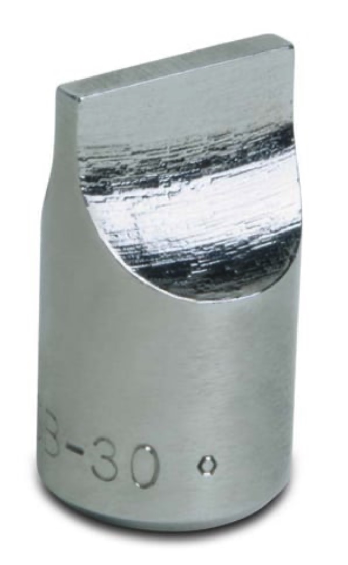
Posted on: 3/29 21:04
|
|||
|
Howard
|
||||
|
||||


