|
Re: 1953 Delco Vacuum Advance
|
||||
|---|---|---|---|---|
|
Home away from home
|
My ’54 copy of “Motor’s Auto Repair Manual” establishes that for the Delco 1110841 distributor the chamber plunger should begin to move at 5-7 inHg, and achieve maximum stroke of 4-6 degrees (distributor) at 11 inHg. I think we can read into this information that the design intent is to have full vacuum advance at cruise power . . . now, what hardware feature establishes the maximum stop?
As I understand that system the spring material & geometry (wire diameter, OD of coil, number of active coils), coupled with the chamber area, establishes the amount of vacuum pressure that is required to stroke from ‘begin to move’ to the maximum stop. The free length of the spring and the shimming establishes the vacuum required to begin the stroke motion. Ross is correct (we would expect nothing less), if only the diaphragm is changed, and you started with all of the correct ‘hard-parts’ then you will likely have a working unit for your car. Now for some intrigue: A few years ago I ran into another detail concerning vacuum chambers for Delco distributors, that is, what feature establishes the ‘high-stop’ limiting the travel of the chamber. The ‘Motor’s’ manual establishes so many inch of mercury to achieve the maximum stop, but otherwise is silent on what feature represents the maximum stop. There are two possibilities, the first case is coil binding in the compression spring, while the second case is a hardware feature that inhibits further diaphragm motion. See attached file for details of what I believe controls the maximum stop. When I mention ‘failed unit’ in the presentation that would be the chamber that was installed in my ’54 Cavalier when I purchased the car, and the ‘replacement unit’ refers to a replacement I bought from one of our trusted suppliers. If I have interpreted the situation correctly the geometry of the opening in the actuation arm controls both the minimum and maximum stop. The maximum stop is therefore not likely achieved by coil binding. I believe Delco would tailor a chamber to the customer’s needs by matching arms and springs, while most of the remaining parts were unchanged, which results in many vacuum chamber part numbers that would physically fit the distributor body, but perhaps have completely different performance characteristics. I believe each arm geometry is identified by a unique number, and there are many arms that will physically fit in a distributor intended for a Packard distributor. The minimum stop arm geometry is likely identical among many Delco units because that is a detail required to specify the free length of the compression spring. My sample size is far too small to draw conclusions, but my concern is there are vacuum chambers with actuation arms that were not intended for Packard applications, or the Packard application has been misidentified. At this point it is speculation whether a rebuilder installed an inappropriate arm (the arm would be re-riveted to a new diaphragm during the rebuilding process), or our supply pipe-line has been contaminated with chambers intended for different automobiles. The search for the patent documents continues. Those document are likely to justify the means to achieve the maximum stop as a ‘unique feature’. I guess what I’m trying to say is “just because the chamber fits the distributor there is no guarantee that the calibration is correct” . . . but if you look at the air gap between the ‘tang’ and the opening in the arm you can estimated the total stroke (some arithmetic required). dp
Posted on: 2023/8/31 19:00
|
|||
|
||||
 VacuumChamber002 [Compatibility Mode].pdf
|
Re: Trunk Rack Swing Hinge Part Numbers
|
||||
|---|---|---|---|---|
|
Home away from home
|
Here’s the rest of the patent application. A lot of parts not yet talked about.
dp
Posted on: 2023/8/9 12:30
|
|||
|
||||
|
Re: 1938 Super 8 thermostat
|
||||
|---|---|---|---|---|
|
Home away from home
|
Kevin: In addition to the spring wire retention there are other designs specifically to be used in cars that never had an OEM thermostat, or a convenient location in the goose neck to install one. The design that I’m familiar with is where a stainless steel T-stat is tack welded to a length of thin walled stainless tubing, and the whole mess is put into the upper radiator hose. If the T-stat is installed at the goose neck end the tubing works its way up the hose until a bend in the hose is encountered. It just sits there until you decide to change it. I’ve had the same one installed in my ‘Brand X’ for 18 years. I did put a good sized (#1 drill) bleed hole just in case the T-stat ended up at the radiator inlet fitting, which is likely considering the upper radiator hose is straight. dp
Posted on: 2023/7/30 13:23
|
|||
|
||||
|
Re: Re-installing rear brake drums
|
||||
|---|---|---|---|---|
|
Home away from home
|
Retuning back to the first few postings from ScottG:
Post 1: As context to the above questions, my car is 1955 Clipper Constellation that is driven regularly and is in reliable mechanical condition. I pulled the drums to locate a slight grinding noise that would arise under hard braking conditions. I found that the secondary shoe was just barely contacting the inner face of the drum which I believe can be corrected with a brake shoe adjustment. Post 6: I only removed the rear brake drums to inspect the shoes and springs after the grinding noise started. After seeing that the shoes were not visibly worn, the retaining hardware was intact and the drum braking surface was not scored, I put everything back together and adjusted the brakes per the manual. I hoped that the shoes simply needed adjusted and that a bit too much travel was allowing the shoe to move outward and contact the inner face of the drum. Unfortunately, the noise never changed although braking performance improved a bit. Post 8: I've put about 2000 miles on the car with no problems and the previous owner was driving it as well. Unless I missed something, the car was braking fine and then starting grinding out of the blue. Post 16 suggests new bearings, axle seals, return springs, hold down hardware, hoses, and rebuilt cylinders. Bearing clearance and brake adjustment were conducted per service manual guidance, yet the noise persists. Post 23: Photos posted to document the locations where the drum web is contacting the shoe(s). This information is indicating one shoe is contacting near the hydraulic cylinder, while the other shoe is contacting near the star-wheel adjuster, essentially diagonal across. Post 27: Basically the brakes were fine and then they weren't. I tried adjusting them, then replacing all the hold-down hardware and return springs, then checking axle bearing clearance (with new bearings and seals), adjusting everything again, and, most recently, disconnecting the hand brake just to make sure it wasn't pulling things out of place. So far nothing has changed the nature of the grinding one bit. At least if I had put something together wrong I could blame myself and then fix the problem. Post 32 documents that the affected drum was ‘cleaned-up’, and there was no objectionable run-out. My take on the symptoms would be: Since for many miles this car did not have the symptom, then the shoes are likely compatible with the drums. There was no mention of the car striking a curb, which would reduce the probability of something is bent, and that accident damage is the root cause of the symptoms. I do like the idea that the shoes are riding too far outward. A few months ago there was a discussion of the numerous lengths of hold down pins, and the precaution to check the length before use. I have first-hand experience on a modern car where the ‘hardware kit’ contained pins that were quite a bit longer than the originals. For all of the symptoms to be explained the original springs would need to have lost a bit of free length, AND the replacement parts are such that the spring force pushing the shoes in contact with the backing plate nibs insufficient. The design intent of that rear axle would be the outer cup of the bearing is in intimate contact with the backing plate, and that sets the spatial relationship between the axle taper and the braking components. The amount of shimming does not change this relationship unless the bearing outer cup has hit a shim instead of the backing plate. That condition would effectively hold the axle taper inboard, and lead to a loss of clearance. That clearance loss would equal the thickness of the interfering shim(s). I would look at the old hold-down hardware versus the newly installed hardware, and I would triple check to make sure the shims are not inhibiting the intended contact between the bearing cup and backing plate. I’ll admit we need a few different failure modes to explain the timeline of all of the symptoms. Unless an axle nut was loose, I’m thinking the initial difficulty could be a relaxed hold down spring, while later in the saga modern hardware may be the culprit, but there remains the shim interference issue. dp
Posted on: 2023/7/29 14:14
|
|||
|
||||
|
Re: Aftermarket Air Conditioning
|
||||
|---|---|---|---|---|
|
Home away from home
|
TxGoat; The web seems to think 3-5 horsepower is the range for AC compressors. As a first estimate the power should vary by speed cubed, and torque by speed squared, so if the 3-5 hp is for a higher rpm then at idle speeds the load is quite small. That by itself may explain why the compressor clutch in my ’54 functions so well, that is the Packard engine speed is quite low therefore the torque never reaches the design point of the clutch, and the fact that the current is essentially ½ of the design current the Packard’s slowness still wins the day.
Howard; The ‘under dash’ evaporator design places the unit essentially in your lap, with little or no duct loss. Perhaps in that configuration a low fan speed still results in acceptable air flow. In the unit featured in the video my bet is all of the controls are hidden under the added panels. The speed switch is set to medium (perhaps at higher speeds an in-line fuse complained), the temperature control set to maximum cooling (minimum temperature), and the single switch is controlling the power to both the blower motor and clutch (open loop unless there’s low & high pressure switchs). Note in the video there is little fan noise. Perhaps an e-mail to Vintage Air is in order. dp
Posted on: 2023/7/9 22:34
|
|||
|
||||
|
Re: Aftermarket Air Conditioning
|
||||
|---|---|---|---|---|
|
Home away from home
|
Howard I’m sitting here trying to figure out if the gentleman converted from 6 v to 12v, only to drop the voltage back down by running the fan at medium speed (likely to limit the current). I must have been absent from class the day that HVAC blower motor voltage discussion took place. My ’54 Cavalier (6+) has a single 3/8 inch belt aftermarket AC system that works just fine. It’s a long belt installation that uses the power steering sheave. The clutch coil has a resistance of 3.6 ohms, which is the same as a 12 v coil in my ’99 Chevy. My evaporator does not seem to have any voltage converter . . . at least not obvious, and I’ve looked. My current thought is the highest fan setting in my car is providing 7+ volts to the blower motor, and that voltage provides enough air flow to convince me the AC is working just fine. I’ve had no success finding an aftermarket evaporator (or blower motor) specifically for 6 volt cars, but I have found a lot of threads that say a 12v AC can’t possibly work on 6 volts! I haven’t found a ‘wide-belt’ solution yet . . . maybe a double 3/8 system would mimic the look, but I suspect a serpentine pulley could be modified.
dp
Posted on: 2023/7/9 20:53
|
|||
|
||||
|
Re: Aftermarket Air Conditioning
|
||||
|---|---|---|---|---|
|
Home away from home
|
Posted on: 2023/7/9 18:35
|
|||
|
||||
|
Re: Looking for information/individual
|
||||
|---|---|---|---|---|
|
Home away from home
|
I don't go back that far in the club, but there are several that do. Try
https://packardsofaz.club/ The club is located in Phoenix. dp
Posted on: 2023/6/16 19:35
|
|||
|
||||
|
Re: Oil Bath Air Cleaner Element Reconditioning
|
||||
|---|---|---|---|---|
|
Home away from home
|
I seem to remember metallic mesh being used in some oil bath air cleaners . . . a lot like a large scouring pad. I went looking on the web and found 6, 3-inch pads for less than $3 . . . stainless steel no less. If the 3M material degrades, SS scouring pads might be a ‘bullet proof’ option. Your right about keeping an eye on mixture, because if the media is too restrictive the mixture will surely enrich. If you suspect enrichment, it will be more severe at higher air flows, but will affect idle as well. A clue would be a different idle mixture adjustment is needed with and without the filter installed. Both the WDO and the WGD carburetors are vented to the engine compartment, and as such would be sensitive to a change in inlet restriction. Remove a spark plug after a bit of exercise to double check. Who knows, with the amount of alcohol in the fuel a bit of extra restriction might be welcomed.
dp
Posted on: 2023/6/10 15:13
|
|||
|
||||
|
Re: Factory Trunk Finish
|
||||
|---|---|---|---|---|
|
Home away from home
|
53 Cavalier;
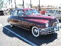
I believe the 26th and 54th (perhaps 24th to 54th) series trunks were finished with the following process: All of interior surfaces of the trunk were sprayed with an undercoating material. The amount of material applied likely varied with location, with the inner surfaces of the rear quarter panels receiving the most, and the spare tire well receiving the least (if any). I believe this coating would be identical to the coating used to adhere the interior sound deadening pads. I’m interpreting the entire surface was sprayed, but I can’t tell unintentional over-spray from an intentional light coat. I believe the goal was to provide more corrosion protection than paint alone, so I’m leaning to the entire trunk was intentionally sprayed. Flocking material was then applied to the interior surfaces, with sufficient flocking material applied to those areas with a ‘heavy’ undercoating to completely cover the undercoating. If an area was going to be covered with a mat/pad/carpet then the flocking would not be applied, and hence the thickness of the undercoating minimized. The next obvious question is what currently available materials would produce the same (or close to) the OEM look and feel. I think just about any black in color roofing cement, or automotive undercoating would be close to the original material, which was/is to encapsulate the steel and thus retard rusting, and be a suitable adhesive for the flocking. POR could also be used if the surfaces are corroded, but that product may be too thin for flocking. The key characteristic for this material is the drying time . . . this material cannot dry in the amount of time it takes to flock the surface. The flocking is another subject entirely. The flocking that survived in my ’54 was inspected under relatively high magnification that revealed a multi-color, multi-length mix of fibers. I read somewhere that the material was goat hair, which would explain the variation in both color and length. The colors ranged from white to black with the majority being tan/light brown. There were a few translucent fibers amongst the mix. The lengths varied in the 1/4 to 3/8 inch range . . . mostly, but there were a few longer and shorter. I realize that I had just vacuumed a 60+ year old car, and was sensitive to the problem of how much of the captured material was modern ‘debris’, and how much was OEM flocking. When I went looking for modern flocking I ran into many choices of color and length, so if my sample to flocking is genuine, many lengths and colors should be blended to mimic the OEM material. If the OEM material was goat hair then I would expect some car to car variation, and perhaps some seasonal variation. Given my sample of flocking fibers I would agree that the overall color would be in the tan/light brown category. The trunk floor on my ’54 had a three piece pad made from ‘tar paper’. The pad was comprised of one rather large piece that covered the floor from the spare tire wheel well to the driver’s side of the trunk floor. It also went from the rear of trunk floor to the beginning of the ‘hump’ for the rear axle. This piece had cut-outs for the various reinforcement gussets along the rear wall of the trunk. Another piece of tar-paper went from the other edge of the spare tire wheel well to the right rear fender. IIRC there was a cut-out for the tire hold-down bolt details. The final piece was filled in the gap between the other two pieces. It is roughly the width of the spare tire well, and filled the gap between the well and the aft wall of the trunk cavity. The piece had a curve to match the well. The three pieces of ‘tar-paper’ were stapled together. I have assumed this covering was to provide some protection from moisture and to protect the fiber-mat/carpet from getting mucked-up from the undercoating. I’m assuming based on the die-cut details this tar-paper pad is original. I have never seen an original upper fiber/carpet pad. My car had an unfolded jack box as an upper pad (ugh!). The void between the rear quarter panels and the outer surface of the wheel tubs was filled with ‘fiber ropes’. My ’54 had what I believe are original items. They are approximately 33 inches long, and 1 ½ inch in diameter. While we use the term ‘rope’ they were made of short fiber paper . . . a lot like crape-paper. The paper was formed into the ‘rope’ such that no edges of the paper were visible, which suggests those edges were facing inward. It also looked like many pieces of paper were ‘stacked’ into a pad prior to folding to hide the edges. A double over-braid of thread with a pitch of approximately 1 inch held the paper bundle together while the ‘rope’ was in storage. The over-braid was a double counter wound configuration that produced a repeating ‘diamond’ pattern. While the ropes for my ’54 had the ends wound with a different type of thread, I don’t believe this was the OEM configuration. I envision a dispenser that would hold many yards of material, and upon activation would dispense a piece of material cut to the correct length. The installer would grip the free end of the material inhibiting the thread from unwinding, and in very short order the material was forced into the fender/tub gap. In my two examples I could not find an obvious splice/gap in the length of the crape-paper, suggesting either those details did not exist in my units, the folding technique could hide those details, or the length of the crape-paper established the length of the final product. Tire kicking wisdom suggests the ropes were installed to inhibit small items from falling between the fender and tub. While this is likely true I believe there is also an argument that could be made for quarter panel support . . . but I do lean to the small item explanation. My ropes did not appear to be flocked . . . but if they were installed just after the undercoating step there would be zero adhesive for the flocking to stick to the ‘ropes’. There was little evidence of undercoating along the length of the ropes suggesting the flocking was applied before the ‘ropes’. I’ve included a few photos of the flocking material, and details of the ropes. You are right about a fun/crafty project. EDIT: Make that crepe paper not crape paper. dp Attach file:  Picture 002A.jpg (297.00 KB) Picture 002A.jpg (297.00 KB)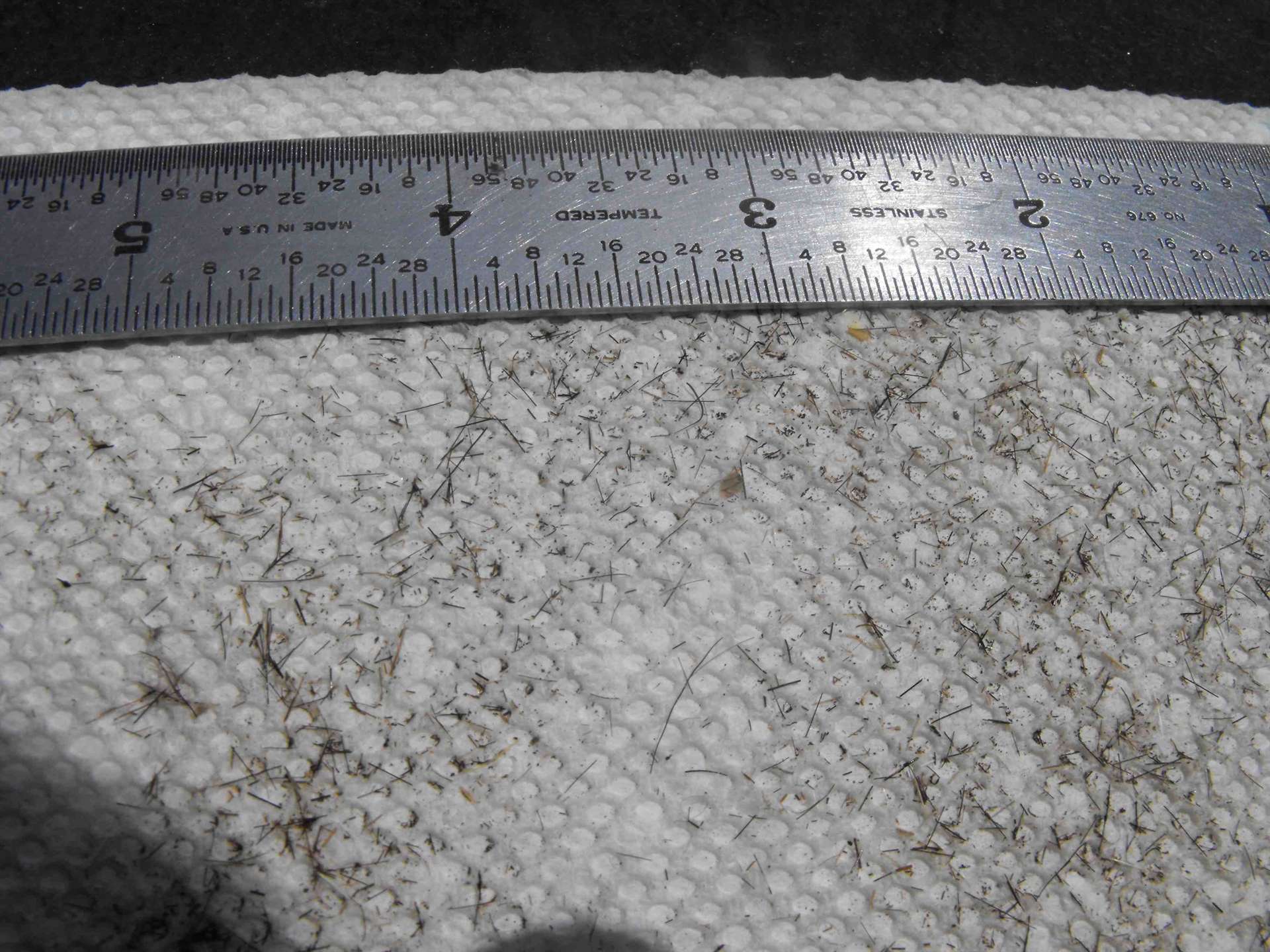 DSCF1003A.JPG (201.37 KB) DSCF1003A.JPG (201.37 KB)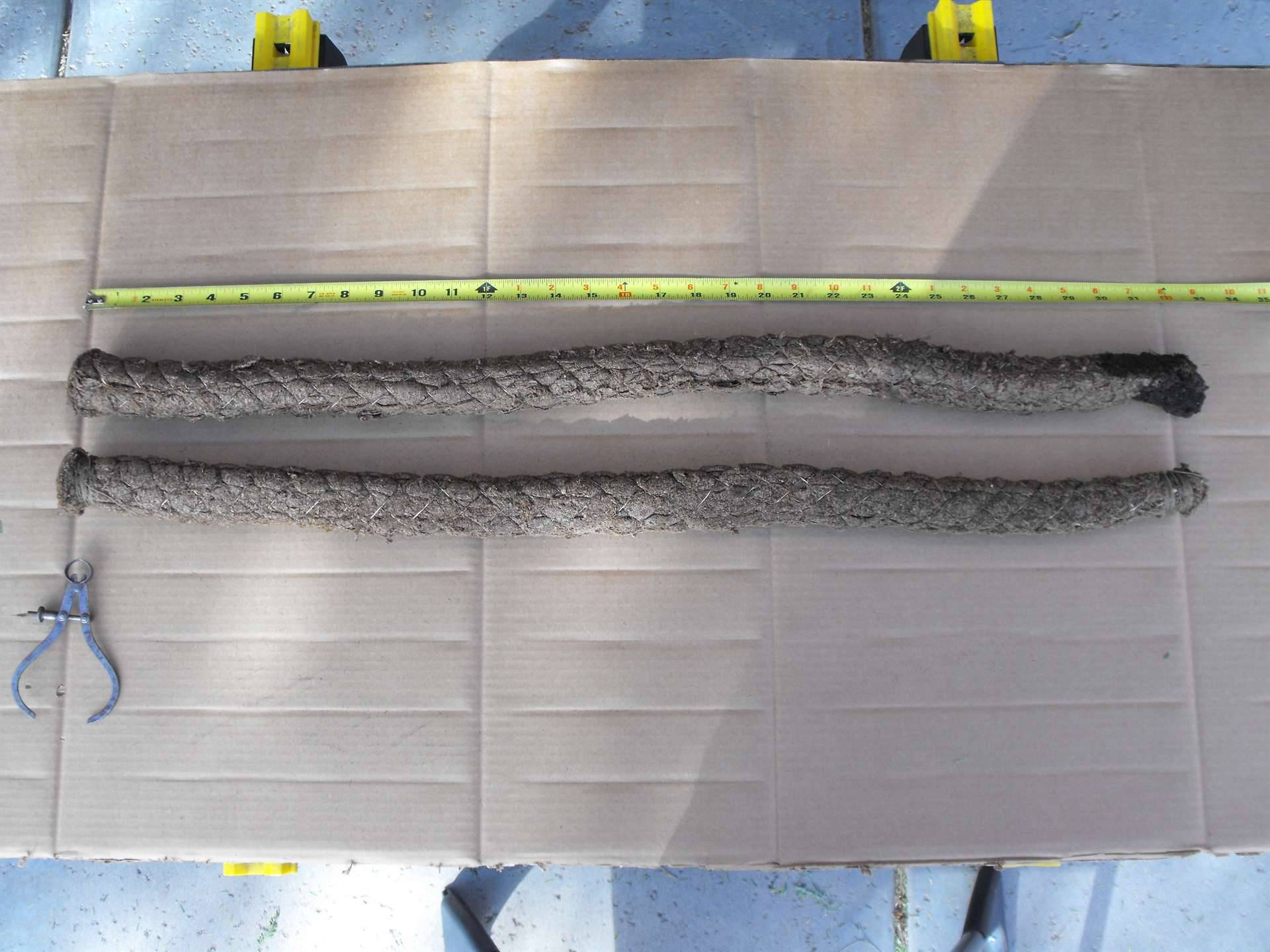 DSCF1011A.JPG (231.69 KB) DSCF1011A.JPG (231.69 KB)
Posted on: 2023/6/1 19:45
|
|||
|
||||


