|
Re: new old topic
|
||||
|---|---|---|---|---|
|
Forum Ambassador
|
The only 21st series factory drawing I can think of is in the annual service counselor showing mechanical specs of the new models Vol 19 #10 of Oct 1945 but like most diagrams until those published later on, it does not cover any of the extra lights or features in a LWB model such as the 2126.
I do not know how the 22nd series LWB wiring actually compares to a 21st series LWB but believe they may be similar enough to be worth looking thru an interior wiring diagram for 22nd series LWB cars in the Dec 15, 1947 SC Vol 21 #23.
Posted on: 2023/6/26 9:03
|
|||
|
Howard
|
||||
|
||||
|
Re: new old topic
|
||||
|---|---|---|---|---|
|
Home away from home

|
Howard.
Again, thank you. I believe that is the reference I was looking for. Really just trying to sort out the basic ignition wiring and generator charging circuits. For now, we will eliminate/decommission the caruretor switch as that has caused some issues on car wanting to restart after it is running. Likely in the OD relay wiring which we hope to correct when new relay comes in. But need to have the engine starting consistently to be able to make the adjustments to timing etc to run consistently. Has only run for 30-45 secon intervals since major overhaul. Looking to get past that. Cheers
Posted on: 2023/6/26 9:20
|
|||
|
Where principles are involved, be deaf to expediency. (Matthew Fontaine Maury 18th century oceanographer)
|
||||
|
||||
|
Re: new old topic
|
||||
|---|---|---|---|---|
|
Forum Ambassador
|
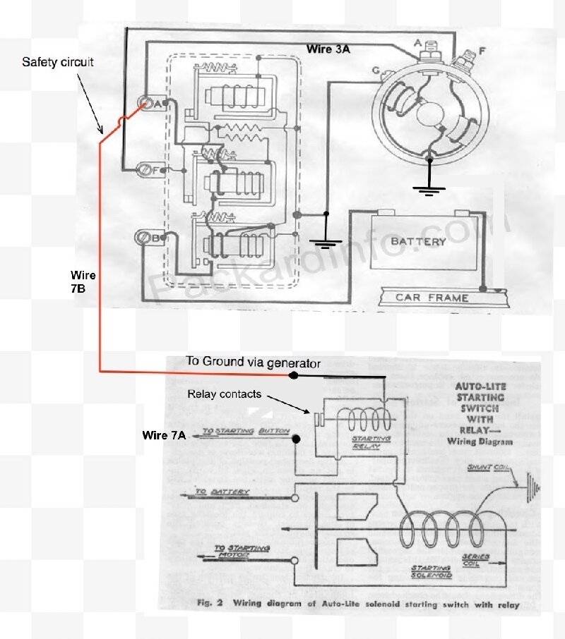
To prevent the accidental starter engagement, in addition to the carb switch and linkage adjustment, in a stock car with the 356 and Autolite gear reduction starter there is also a safety circuit that prevents the solenoid start relay from getting a ground and being able to operate when the engine is running and generator is charging. That is handled by wire 7B in the drawing just referenced.
The circuit works by connecting one side of the small start relay inside the solenoid to the ARM terminal of the regulator so relay gets ground thru the non running generator armature windings. When engine is off, power comes thru the carb switch on 7A to power one side of the relay. Ground comes in via the 7B connection to regulator. It originates thru generator armature windings which are ultimately connected to case ground and travels to regulator via 3A. With power on one side and ground on the other the relay will pull in and solenoid engages. After the engine starts and generator starts charging, voltage out from generator is now on 3A instead of ground. Since it is also tied to the solenoid relay, that voltage is present via 7B to the relay coil. With voltage on both sides of the coil there is no differential so relay cannot pull in and starter cannot engage when the engine is running and generator is working. Engines other than the 356 did not have this circuit and even some 356 engines did have the circuit bypassed if there were instances of engines occasionally not starting due to charging or generator issues. On those engines the linkage and carb switch adjustment as well as proper functioning of the vacuum operated ball inside the carb disconnecting accelerator linkage from the switch actuation piece is critical to prevent the issue you are experiencing. Here is a basic drawing of the safety circuit with the 47 wire labels included. Subtle variations of this circuit was in use on 356 models from 40 thru 50 and drawings show it was also used with a different starter in the senior 327 motors in 51-2.
Posted on: 2023/6/26 9:58
|
|||
|
Howard
|
||||
|
||||

 356 with Autolite solenoid and safety ground circuit.jpg (99.50 KB)


