|
Re: 48-50 Bimetal Senders Retrofit Project
|
||||
|---|---|---|---|---|
|
Home away from home
|
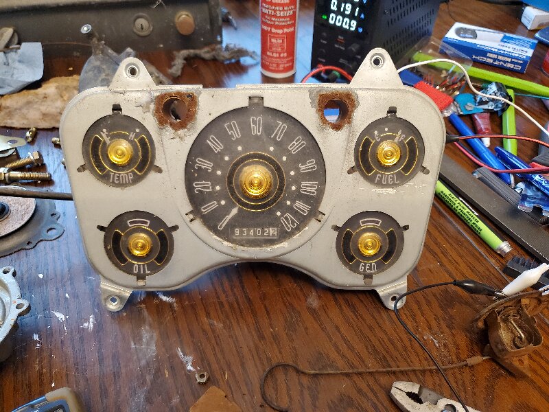
I did some testing on my Clipper instrument cluster. Both the gas and temp gauges started to move with 0.05A and negligible voltage drop. They read completely pegged up the scale at 0.22 and 0.26 amps with about a 4 volt drop.
Of course, some quick math with Ohm's law gives that you would need a 4 ohm sender for the gauge to read this high. So what about our 13 ohm senders? On my fuel gauge I found that if I tweaked the sender internal arm to read 10 ohms high instead of 13, it ends up right on the dot. However, I attached this adjusted gauge to my temp gauge and it made it read only 80% of the way up. For whatever reason, the fuel gauge has some overshoot with respect to the dot labels, but the temp gauge does not. You can actually see this; the fuel gauge right dot is to the left of the F, but the temp gauge right dot is to the right of the H. And yes this is from a straight on perspective as well as a driver's perspective.
Posted on: 2024/5/28 19:05
|
|||
|
1955 400 | Registry | Project Blog
1955 Clipper Deluxe | Registry | Project Blog 1955 Clipper Super Panama | Registry Email (Parts/service inquiries only, please. Post all questions on the forum.) service@ultramatic.info |
||||
|
||||
|
Re: 48-50 Bimetal Senders Retrofit Project
|
||||
|---|---|---|---|---|
|
Forum Ambassador
|
What would be interesting would be to find a 48-50 gauge and compare the two current requirements and ohm readings of the heaters. They are both King-Seeley heater actuated bimetal strip gauges but the 48-50 gauges that use the bimetal sender with another heater in series that provides on/off pulses are powered directly from the battery via the ign sw so run at 6.3 to 7.3 volts. The 51 and later gauges use an instrument voltage regulator that provides a supply that is called a constant voltage (even though it is pulsing) where the pulses are averaged and is specified as 5v. Those gauges use the changing 73-10 ohm straight resistance sender. The only thing I can definitely say about the gauges is one type sender does not provide a proper reading on the other type gauge.
Posted on: 2024/5/28 20:32
|
|||
|
Howard
|
||||
|
||||
|
Re: 48-50 Bimetal Senders Retrofit Project
|
||||
|---|---|---|---|---|
|
Home away from home
|
Ok so I "KNEW" that something like this must already exist. But good lord why is it $100??
Maybe I should break into this market... tanksinc.com/index.cfm/page/ptype=product/product_id=748/mode=prod/prd748.htm
Posted on: 2024/6/11 19:52
|
|||
|
1955 400 | Registry | Project Blog
1955 Clipper Deluxe | Registry | Project Blog 1955 Clipper Super Panama | Registry Email (Parts/service inquiries only, please. Post all questions on the forum.) service@ultramatic.info |
||||
|
||||
|
Re: 48-50 Bimetal Senders Retrofit Project
|
||||
|---|---|---|---|---|
|
Forum Ambassador
|
Thanks for posting. That is quite a gadget and definitely more than just a basic analog converter -- microprocessor based probably since the calibration values need to be saved so that, plus it is probably one of a kind, and then a bit of profit would explain the $90. Be very interesting to see if it would work the 48-50 gauges using a commonly available modern aftermarket resistance sender in place of the bimetal. Question might be if the unit and aftermarket sender would be comparable in price to a repro Ford sender. Believe it was recently proven the Ford temp sender would work and fit the Packard so their oil and gas senders should as well but the ability to use any easily found sender and fine tune the gauge reading and the low or high level warning indicator might be a plus.
Assuming it worked the gauge, specs say 7v is the low end of input voltage supply range so wonder if that is absolute or if there is a margin. If no margin, it would probably be OK when engine is running and charging but maybe questionable and fussy like the Pertronix is at 6v when just sitting -- particularly if hooked up to some of the dirty terminals and overall poor wiring many cars are running around with. Guy doing video said supply current need was minimal so could probably add a small 6 to 12v step up converter if needed.
Posted on: 2024/6/11 22:22
|
|||
|
Howard
|
||||
|
||||
|
Re: 48-50 Bimetal Senders Retrofit Project
|
||||
|---|---|---|---|---|
|
Home away from home
|
That's true, but in that case you can do what Kev mentioned and just make it MC powered. For example the STM32F103C8T6 is a popular chip. It runs on 3.3V logic so you could use it on any vehicle voltage. It also includes tons of internal flash for storing nonvolatile data. And it's like $1 if you buy through a PCB manufacturer.
All you do is pick up a development board from eBay for a couple bucks and start breadboarding. The programming software is free from ARM and it connects via USB. There are two onboard ADC's for processing a reference voltage. Pretty sure you would only need one. Then use something like a TPS5430DDAR as an output driver. The same could be used as a step down regulator for the MC itself. Actually for a non microcontroller one I thought of something even simpler, which is to use two "adjustable Zener" regulators to give set points. But I would have to think about that some more.
Posted on: 2024/6/12 6:51
|
|||
|
1955 400 | Registry | Project Blog
1955 Clipper Deluxe | Registry | Project Blog 1955 Clipper Super Panama | Registry Email (Parts/service inquiries only, please. Post all questions on the forum.) service@ultramatic.info |
||||
|
||||


 20240528_194935.jpg (464.53 KB)


