|
Re: 1955-56 Senior instrument cluster
|
||||
|---|---|---|---|---|
|
Forum Ambassador

|
would compressed air work on the oil pressure gauge?
Posted on: 2016/9/6 10:47
|
|||
|
1937 Packard 138-CD Deluxe Touring Limousine
Maroon/Black 1090-1021 [url=https://packardinfo.com/xoops/html/modules/registry/View.php?ID=232]1955 Packard |
||||
|
||||
|
Re: 1955-56 Senior instrument cluster
|
||||
|---|---|---|---|---|
|
Forum Ambassador

|
You MUST use the regulator to power the gauges and I think since Clippers used the same item it should have at least two gauges connected to the regulator to have an adequate load. Three gauges were connected in the Packard. The regulator needs to be grounded to work but the gauges do not.
The regulator is a chopper device operated by a heater and bimetal strip which pulses 6 or 12v on and off with a frequency and duration that would average 5v being supplied to the gauges. Due to the on/off operation of the regulator it is somewhat hard to get an accurate voltage out reading with a typical VOM. The senders have a range of 10 ohms at the full, hot or high pressure end and roughly 73-75 ohms at the empty, cold, or low pressure end. The suggested Packard method of checking was to use a spare fuel sender and connect that to the questionable gauge. Service Counselor 27 #10 has the procedure.https://www.packardinfo.com/xoops/html/downloads/SC/SC-VOL27NO10.pdf They are testing on a 52 but the 51-56 gauges are the same electrically so the procedure and results are identical. I don't have any info on the ammeter. Most VOMs have a limited amp measurement range of max 10amps or so. You could find something you can hook in a circuit that is within that range. Measure that with the VOM and then see what the ammeter does with the same item. As someone pointed out recently, in most years Packard called it a battery charge indicator and not an ammeter. I do not know if there is a precise correlation between 10 amps on a meter to a specific deflection of the needle on the gauge. Max generator output was 30 amps so one would think that would be close to full scale on the gauge but since we don't know the capacity or if the gauge is linear that is not a given. Here is what the output of the regulator looks like. On this example, voltage out is approx 12.6v, duration of pulse about 90-100 ms and frequency about every 400 ms. Those are variables that change by supply voltage in and also by the gauge load in the circuit to get to the average 5v output. I don't remember if I had two or three gauges connected -- three I think. Attach file:  (113.04 KB) (113.04 KB)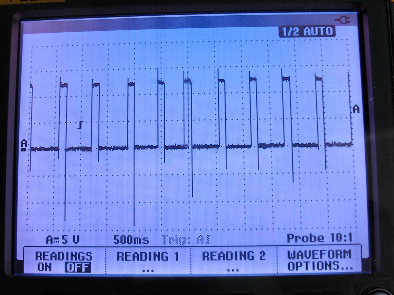
Posted on: 2016/9/6 11:03
|
|||
|
Howard
|
||||
|
||||
|
Re: 1955-56 Senior instrument cluster
|
||||
|---|---|---|---|---|
|
Home away from home
|
Anyone think replacing packard voltage regulator witn an electronic one be better.
I would think it would be more accurate. Giving constant 5 volts. Buck converters are cheap.
Posted on: 2016/9/7 9:45
|
|||
|
Riki
|
||||
|
||||
|
Re: 1955-56 Senior instrument cluster
|
||||
|---|---|---|---|---|
|
Home away from home
|
Anyone think replacing packard voltage regulator witn an electronic one be better.
I would think it would be more accurate. Giving constant 5 volts. Buck converters are cheap.
Posted on: 2016/9/7 9:47
|
|||
|
Riki
|
||||
|
||||
|
Re: 1955-56 Senior instrument cluster
|
||||
|---|---|---|---|---|
|
Forum Ambassador
|
There have been some modern solid state regulators installed. I don't remember the number that was mentioned as working other than it was a Ford item. Apparently it took some experimentation because as I remember the discussion the poster had at least one failure before hitting on the right one. There are some home made kits or schematics to build your own available too. Don't know if anyone has tried one of those.
One issue with solid state is the load needs to be appropriate for the regulator. I have no idea what the Packard load with two or three gauges might be but Ford has several versions for their various models. They all look very similar on the outside so differences must be in the electronic section. Unfortunately the catalogs don't give specs for the output capacity -- only the model cars the regulators were for. The main problem with going the solid state route is that they are polarity sensitive. AFAIK the regulators only come in negative ground. That leaves the 55s and earlier out unless changes are made. Like other solid state replacements, an accidental polarity swap as has happened to our Packards would also be an issue.
Posted on: 2016/9/7 10:07
|
|||
|
Howard
|
||||
|
||||
|
Re: 1955-56 Senior instrument cluster
|
||||
|---|---|---|---|---|
|
Home away from home
|
Thanks h.
Wonder if putting a capacitor to ground would help. As in filtering the wave.
Posted on: 2016/9/7 10:19
|
|||
|
Riki
|
||||
|
||||
|
Re: 1955-56 Senior instrument cluster
|
||||
|---|---|---|---|---|
|
Home away from home

|
Riki Quote:
Wonder if putting a capacitor to ground would help. As in filtering the wave. On the 12v regulator on my bench gauge cluster, there is already a capacitor on it at the chopper, but the schematic does not show it, so maybe it was an add-on. My multimeter in DC mode reads 12V out of the "5V" [squarewave] output and I don't have an oscilloscope to see what it actually looks like. The gauges all work except the ammeter (which does not move), but they are acting weird. They keep increasing the reading from min to max like maybe they were seeing 12V, not 5V. I'm pulling the gauge cluster out of my 56 400 parts car to see how it behaves. Craig
Posted on: 2016/9/7 12:36
|
|||
|
Nuke them from orbit, it's the only way to be sure! Ellen Ripley "Aliens"
Time flies like an arrow. Frui |
||||
|
||||
|
Re: 1955-56 Senior instrument cluster
|
||||
|---|---|---|---|---|
|
Home away from home
|
How about a 12V to 5V DC converter like this one?
https://www.amazon.com/DROK-Waterproof-Converter-Adjustable-Transformer/dp/B00C0KL1OM/ref=pd_lpo_23_tr_img_2?ie=UTF8&psc=1&refRID=Z7NH7WSSDW6GJXFD3VQ0 Craig
Posted on: 2016/9/7 12:39
|
|||
|
Nuke them from orbit, it's the only way to be sure! Ellen Ripley "Aliens"
Time flies like an arrow. Frui |
||||
|
||||
|
Re: 1955-56 Senior instrument cluster
|
||||
|---|---|---|---|---|
|
Forum Ambassador
|
Specs sound good for 12v neg ground cars so in theory it should work well and at less than $10 worth testing.
Not sure about positive ground cars because of the common ground in the unit. If both sides were reversed with the pos output connected to ground it might work. The gauges wouldn't care about polarity but without knowing how it is connected internally it could self destruct. One of the notes says input voltage should be 3v more than the output so wonder how stable it would be or if it would work at all on 6v cars.
Posted on: 2016/9/7 13:09
|
|||
|
Howard
|
||||
|
||||


