|
Re: Power Antenna Wiring
|
||||
|---|---|---|---|---|
|
Forum Ambassador
|
It does not sound like that switch or wiring is stock Packard either. The wiring from factory should be as shown with a 20amp inline fuse in the red wire from ign switch to ant switch. That motor (as does almost all reversible motors that Packard used has 2 separate coils, one for each direction) The mounting screws to body provide one conductor and ONE of the wires depending on direction connects to a voltage and provides the other. There should be no place on switch for any additional wire to hook up, nor do the wiring diagram show any connection to fuse block.
Attach file:  (9.97 KB) (9.97 KB)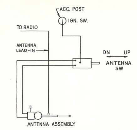  (11.48 KB) (11.48 KB)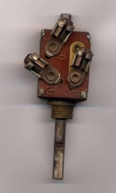
Posted on: 2008/12/20 10:41
|
|||
|
||||
|
Re: Power Antenna Wiring
|
||||
|---|---|---|---|---|
|
Home away from home
|
JUst got back from auto parts buying fuses. Will take pic and post in three minutes.
Okay, here's the pic. Note the two wires circles in black go to motor. The one circled in white goes to fuse box. The one circled in red was disconnected. With car running, I touched the onec ircled red to the vacant contact point, got a spark and fuse blew. Note also that one circled red is spliced into one circled whire (see electrical tape). Also, note that the fuse slot at fuse box is labeled "Washer" ( Go figure!  ) )Attach file:  (37.20 KB) (37.20 KB)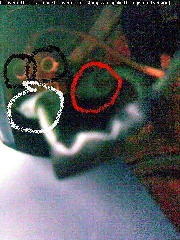
Posted on: 2008/12/20 11:11
|
|||
|
||||
|
Re: Power Antenna Wiring
|
||||
|---|---|---|---|---|
|
Home away from home
|
While. we're at it. Why connect to ignition? Does that make ant. go up and down when car is started and turned-off? If that's the case, then, why the control knob?
Posted on: 2008/12/20 11:27
|
|||
|
||||
|
Re: Power Antenna Wiring
|
||||
|---|---|---|---|---|
|
Home away from home
|
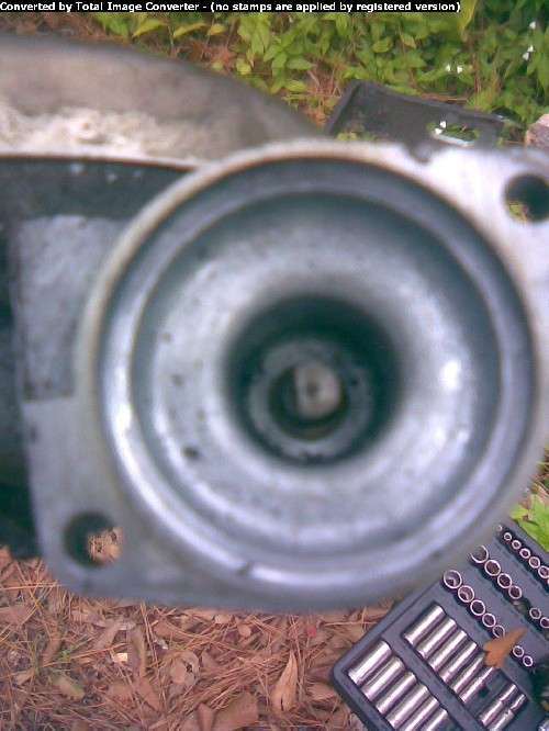
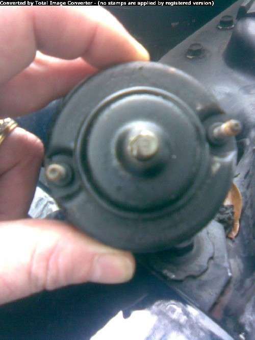
Also, here's two more pics to show the way motor connects to antenna. I don't get it because there are two half-moon shaped spindles. One doesn't fit in the other, so how does it work. Is there some sort of magnetic grip that pulls the spindles together to rotate the spindle on the antenna side?
Posted on: 2008/12/20 11:38
|
|||
|
||||
|
Re: Power Antenna Wiring
|
||||
|---|---|---|---|---|
|
Forum Ambassador
|
I'd need to see more of antenna, but don't recognize that as Packard. Do you have a single on front fender or duals on back? This photo I borrowed from cli55er's blog shows one type front 55-6 antenna, and there's another version almost identical but with the nylon storage in a long loop about 2' high instead of compact coil. It sounds like who ever converted the washer to all electric did some other changes.
Did that extra wire get pulled off that electric washer setup by chance. Know it's hard under dash for picts but can't see enough detail in the antenna sw to make any suggestions. If the switch is one shown in post above, then that is correct one and the antenna would connect to the U & D on one side and battery to the long B on opposite. Anything other and need to see a detailed photo to offer much help. As to the ign sw hookup, that was a convenient place that was on only when ign sw was in run or acc position. Has nothing to do with automatic operation. As you noted, there is no acc post on fuse block as such, so switch was the place used for lots of accessories. They would have individual wires with fuses connected there to get a hot lead. Attach file:  (6.38 KB) (6.38 KB)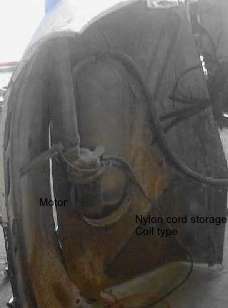  (10.99 KB) (10.99 KB)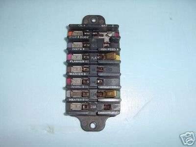
Posted on: 2008/12/20 11:58
|
|||
|
||||
|
Re: Power Antenna Wiring
|
||||
|---|---|---|---|---|
|
Home away from home
|
Single on fender. The nylon is in a 3, maybe 3.5", diameter casing. I already opened it and checked it. It is fine.
Posted on: 2008/12/20 12:04
|
|||
|
||||
|
Re: Power Antenna Wiring
|
||||
|---|---|---|---|---|
|
Forum Ambassador
|
That motor almost looks like one from a rear antenna--maybe someone mounted that style instead?? The rears were short--about 16 inches total length and had a large 5-6" diameter metal enclosure just above the motor where the excess nylon cord was pulled around a reel. Motor shaft on those fit into a mating hole in the worm type gear that drove the reel. Wiring was the same. Grounded case plus a single hot for whatever direction.
Posted on: 2008/12/20 12:07
|
|||
|
||||
|
Re: Power Antenna Wiring
|
||||
|---|---|---|---|---|
|
Home away from home
|
Next pic coming your way.... Okay, it's still not a great pic. You cand see "D" for down. "U" is the one right below it.
I can't make out anything on the connector for the top right. That was the vacant one. It looks like it is not labeled, but it certainly could be (it's hard to see). The connector on bottom right was connected. I can't make out any labeling there, either. The connector on the top right is just a tiny rectangular conector where the connector on the wire just slips over it. I don't know what you call that type of connector, but it's very common. Just a friction fit. One I am trying to avoid is blowing more fuses, over and over, while I diagnose this thing. Two points: First, I have the antanna out of the car and disconnetced from the motor. The more is still connected to the electrical, but not to where it mounts to the antenna. I just thought I would try and see if the shaft in the motor turns. Perhaps when I hooked up the other wire, I got power but it was not properly grounded? Does the motor need to be mounted to antenna for proper grounding? Attach file:  (31.80 KB) (31.80 KB)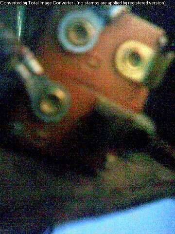
Posted on: 2008/12/20 12:19
|
|||
|
||||
|
Re: Power Antenna Wiring
|
||||
|---|---|---|---|---|
|
Home away from home
|
Here is another pic: Maybe better???
Here, you can see the connections on right better. These are NOT the up and down connections. The top right is the one not connected. It has the friction fit standard connection (whatever you call it). The one on the bottom right is screwy. You can see it is more or less cylindrical with a groove cut into it. A rectangular sheet metal connector on the wire slides somewhat haphazardly into the groove. That was the one that used to be connected. Attach file:  (36.52 KB) (36.52 KB)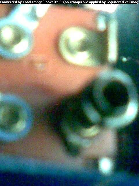
Posted on: 2008/12/20 12:29
|
|||
|
||||

