|
Re: Snapey's 1935 Racing Biposto
|
||||
|---|---|---|---|---|
|
Home away from home
|
Hi 55 - glad you have enjoyed the ride so far.
Hmmm - a cross flow side valve... it's good to see someone else with a perverted sense of the practical like myself LOL. The conversion would be neigh on impossible using any existing block that I know of, as you would require the block surface to seat the valves in and an additional cam to operate them. Although it may well have been played with 'in the day' I think that the natural restrictions that exist to air flow in the side valve design when you are trying to keep compression ratios relatively high would have stopped development. Although now I think about it I am pretty sure that Packard did build a number of V12 aircraft engines that used a central cam shaft to operate valves on both sides of the cylinder???? I would have to go back to my 'Master Engine Builders' book to be sure. My father is currently developing a supercharged, methanol burning race engine for use in one of his period based specials, which uses an in line 4 cylinder 'F-head' Willys engine. The inlet valve is overhead and the exhaust is side-valve and this provided approx 25% more power than the same engine capacity in standard side-valve format in its day. The inlet valve is HUGE and he hopes to get well above 200hp from this 2.25 litre engine. As for the 'Commer Knocker', Commer was the brand name of these trucks built by the Rootes Group and the 'Knocker' was the nick name given to the truck because of the distinctive noise it made. It was an unusual engine with 3 pairs of pistons which worked opposeded to each other in 3 cylinders and then drove to a single crank shaft using a connecting rod and rocker assembly. The supercharger acted to 'scavange' the cylinder meaning the engine ran as a 2 stroke with piston exposed ports. Indeed it think it very English in that it is so different but also in the fact that it worked rather well - the only weak link being the shaft that drove the blower. Check outhttp://en.wikipedia.org/wiki/Commer_TS3 for more information.
Posted on: 2011/6/22 2:34
|
|||
|
If at First You Don't Succeed - Skydiving is Not For You...
|
||||
|
||||
|
Re: Snapey's 1935 Racing Biposto
|
||||
|---|---|---|---|---|
|
Home away from home
|
Thanks for the info on the Commer Knocker; I followed it around a bit on youtube and even found a working cutaway. Fascinating. What a wonderful sound under load.
A far as crossflow flatheads are concerned, they are called "T-heads" with a valve on either side of the piston, and that is actually a very old design used by Mercer and others. That layout causes a huge combustion chamber and thus low compression. Point of fact, I cut my lawn yesterday with a "crossflow flathead" in my 1954 Gravely L tractor. Those are greatly beloved lawn tractors over here. My father bought it new; I have cut grass with it for 46 seasons. Sorry for the hijack.
Posted on: 2011/6/22 5:00
|
|||
|
||||
|
Re: Snapey's 1935 Racing Biposto
|
||||
|---|---|---|---|---|
|
Home away from home
|
Yes, of course, the T-head. You must forgive me but it has been one of those days...
As you say it is not a design that can provide decent compression ratios and when you think about it, as soon as you start to try to create additional valve lift or increase the size of the inletting in the head to improve gas flow, the situation will become even worse. I am facing the very same quandry with the 282 motor. With what are relativly small valves (and without much room to increase their diameter) it means that to improve flow I will need to increase the valve lift. Also with the valves so closely spaced increasing the overlap could also become a problem. Luckily I have access to many years of 'research' via my family and it is a problem that I will very happily hoist off onto my father and/or brother. They are better at this sort of thing than I am and if it all turns pear shaped I will have someone else to blame... althought the chances of either one of them copping to that are pretty slim. Anyway, as previously discussed I will be trying to create a new 2 piece head modelled on the very effective 2 piece unit that we currently use on one of our Willys engined specials - the one that I normally drive in competition (photos of which you will find here -http://clubs.hemmings.com/clubsites/wocv/willywilly/willyrac_07.htm ). I figure this will be pretty simple - just double a straight 4 cylinder design to get a straight 8 head... easy... Actually it is easier than you might think, especially given that this is the sort of thing that I am actually good at. Well, I assume there is a reason that people are willing to pay me to do this sort of thing - and I'm pretty certain that it is not because of my stunning good looks... ROFLMAO!
Posted on: 2011/6/22 7:47
|
|||
|
If at First You Don't Succeed - Skydiving is Not For You...
|
||||
|
||||
|
Re: Snapey's 1935 Racing Biposto
|
||||
|---|---|---|---|---|
|
Home away from home
|
Quote:
Could sinking one or both of the valve seats deeper in the head provide for greater width? Of course, this would result in "shrouding" and also affect combustion chamber pressure. But, remember the extra flow you'll get from the blower. You might be looking for a problem that you won't have. Quote: http://clubs.hemmings.com/clubsites/wocv/willywilly/willyrac_07.htm ). I figure this will be pretty simple - just double a straight 4 cylinder design to get a straight 8 head... easy... I agree, with your obvious skills and access to equipment, this will not be too hard. Multiple cylinder heads for in-line engines have already been used with good results. International Harvester did it on their crawler tractor engines. 6-cylinder in-line diesel (overhead valve) engines had two "3-cylinder" heads that were torqued individually to the block. The block, of course was over 4 feet long (I estimate), so a full-length head bolted to it would naturally tend to buckle and crack. In fact, the short heads were even prone to cracking. So, another reason for the split head design is maintenance. Possibly just one head needs repair and it's much easier to remove and transport 250 pounds at a time instead of 500 (not really exaggerating much because each included valves and rockers). SO, separate 4-cylinder heads for a straight-eight automotive engine should be a strength, not a weakness. It's probably been done on other engines, I just happened to be personally familear with an International 6-cylinder in a TD 18 crawler tractor. Now, about those 2-cycle engines and "scavenging" exhaust from cylinders during the downstroke, using crankcase pressure and ports in the cylinder walls, any old Lawnboy mower gives a great example of how well this works. As most of you know, plenty of other 2-cycle one or two cylinder engines use a similar design. The advantage is: no blower needed, eliminating moving parts and parasitic drag. This leads back to my flathead. valveless engine... each cylinder could have a discreet crankcase that would used its own pressure on the downstroke to scavenge the cylinder of gases and re-fill with air/fuel mixture. Of course, some type of oil injection or oil-mixed fuel would be necessary in that case. Otherwise, a blower would be needed. Next, to eliminate the ignition system as well... think gasoline powered engines for model airplanes and cars, but on a larger scale. The downside to all of this is, of course, emissions. But on a race car, this is not an issue, and the whole point of posting these thoughts is to make sure you're using every possible crazy idea on this Biposto. It's beginning to look like this might end up being your bucket-list vehicle, after all, so it must make a complete statement of your personal values and tastes, or lack thereof. 
Posted on: 2011/6/25 15:14
|
|||
|
Guy
[b]Not an Expert[/ |
||||
|
||||
|
Re: Snapey's 1935 Racing Biposto
|
||||
|---|---|---|---|---|
|
Home away from home
|
On the topic of strange engines, in the early 1930's two brothers named Chamberlain (from Melbourne, I think) built an 8 cylinder, 16 piston,two crank, S/C, front wheel drive, 2 stroke special. There is very little information around the web on this car, but it still exists and runs occasionally.
I found some photos of it here -http://www.flickr.com/photos/sjhearn/162807113/in/set-72157594159273818/
Posted on: 2011/6/26 6:46
|
|||
|
If at First You Don't Succeed - Skydiving is Not For You...
|
||||
|
||||
|
Re: Snapey's 1935 Racing Biposto
|
||||
|---|---|---|---|---|
|
Home away from home

|
If you want to go crazy let's go crazy. How about an F head cylinder head to fit your block. Use both existing valves for intakes. Cast an aluminum head with 1 big exhaust valve or 2 small ones if you prefer a 4 valve setup.
The rule is the exhaust valve should be 80% the size of the intakes so you will probably need to use 2 in order to keep them small and light enough for fast action, and to avoid burning. Run the exhaust out the far side and there you are with your 4 valve crossflow engine. The head would need to be OHC. This would be crazy difficult and expensive for a 1 off but not as bad as it used to be. With today's CAD CAM , lost foam casting and other advanced techniques it is not as expensive to go from concept to castings. In the end you might get max HP up to practically the same as a stock OHV V8 of the fifties of similar size.
Posted on: 2011/6/26 9:43
|
|||
|
||||
|
Re: Snapey's 1935 Racing Biposto
|
||||
|---|---|---|---|---|
|
Home away from home
|
You are all starting to worry me a great deal... LOL. I think if I were to go to that much trouble I would have to look seriously at a twin overhead cam set up. Jesse Vincent did it in 1926/7 after returning from Europe where he visited with Bugatti in Paris and took a tour of the Mercedes factory in Germany. He modified a straight 8 'senior' engine - so why not us?
Anyway, I finally got around to taking a few pictures of the latest developments tonight. I even balanced the RO34 blower roughly in position but as you can see from the chalk 'cut here' lines much will change at the front end. No more work has been done to date as we were away last weekend, but I'm looking forward to some quality 'shed time' this weekend when the BW attends a friends baby shower. Sunday morning (at least) will be spent at one of the big swap meets held each year here in Sydney. There are a few items on the shopping list including a 17x4" wheel or two to suit, front shock absorbers, carbs, headlights and a steering wheel would be nice... Attach file:  (96.30 KB) (96.30 KB)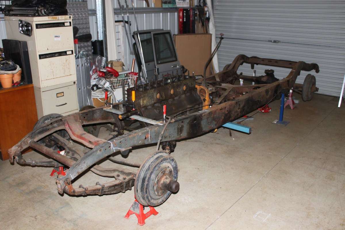 (85.95 KB) (85.95 KB)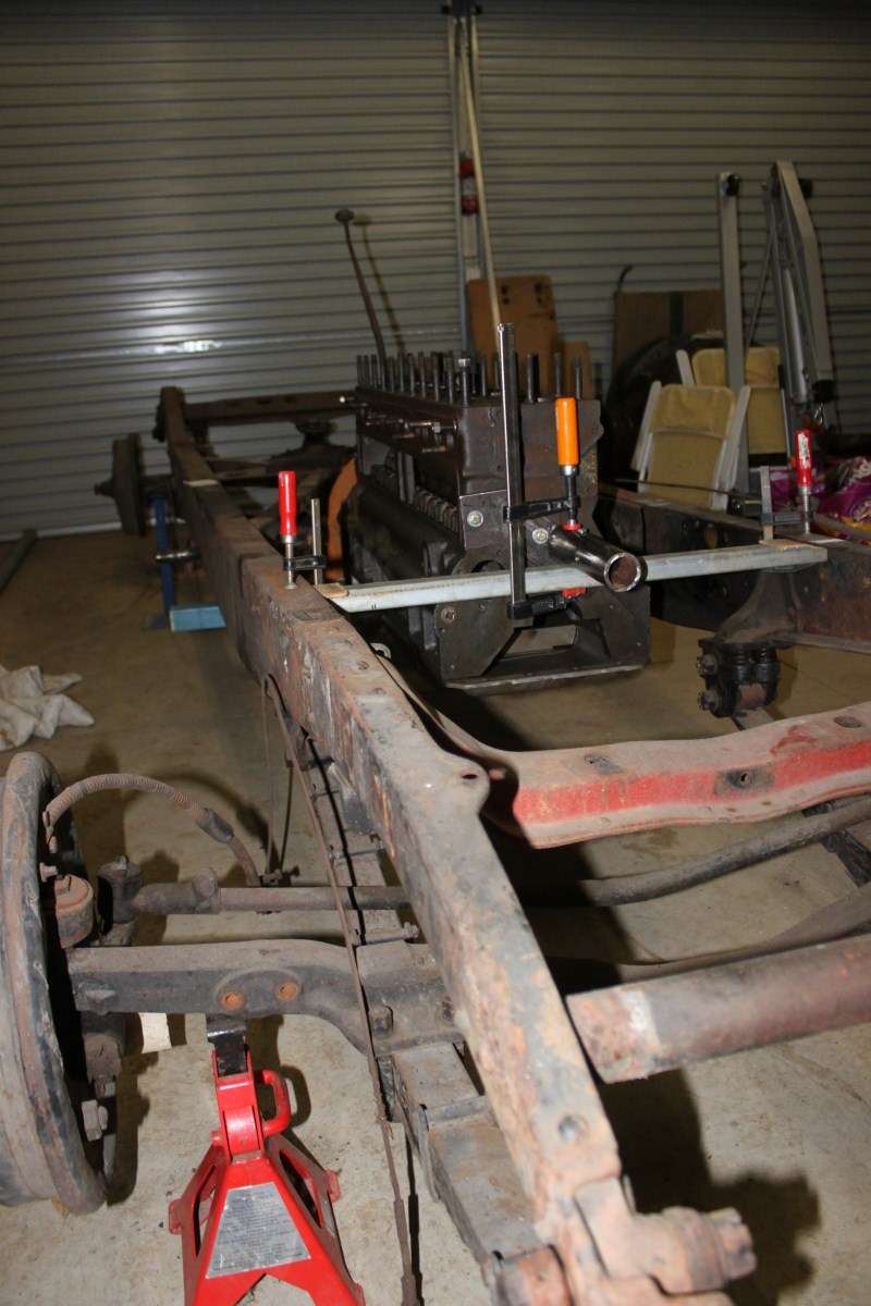 (88.00 KB) (88.00 KB)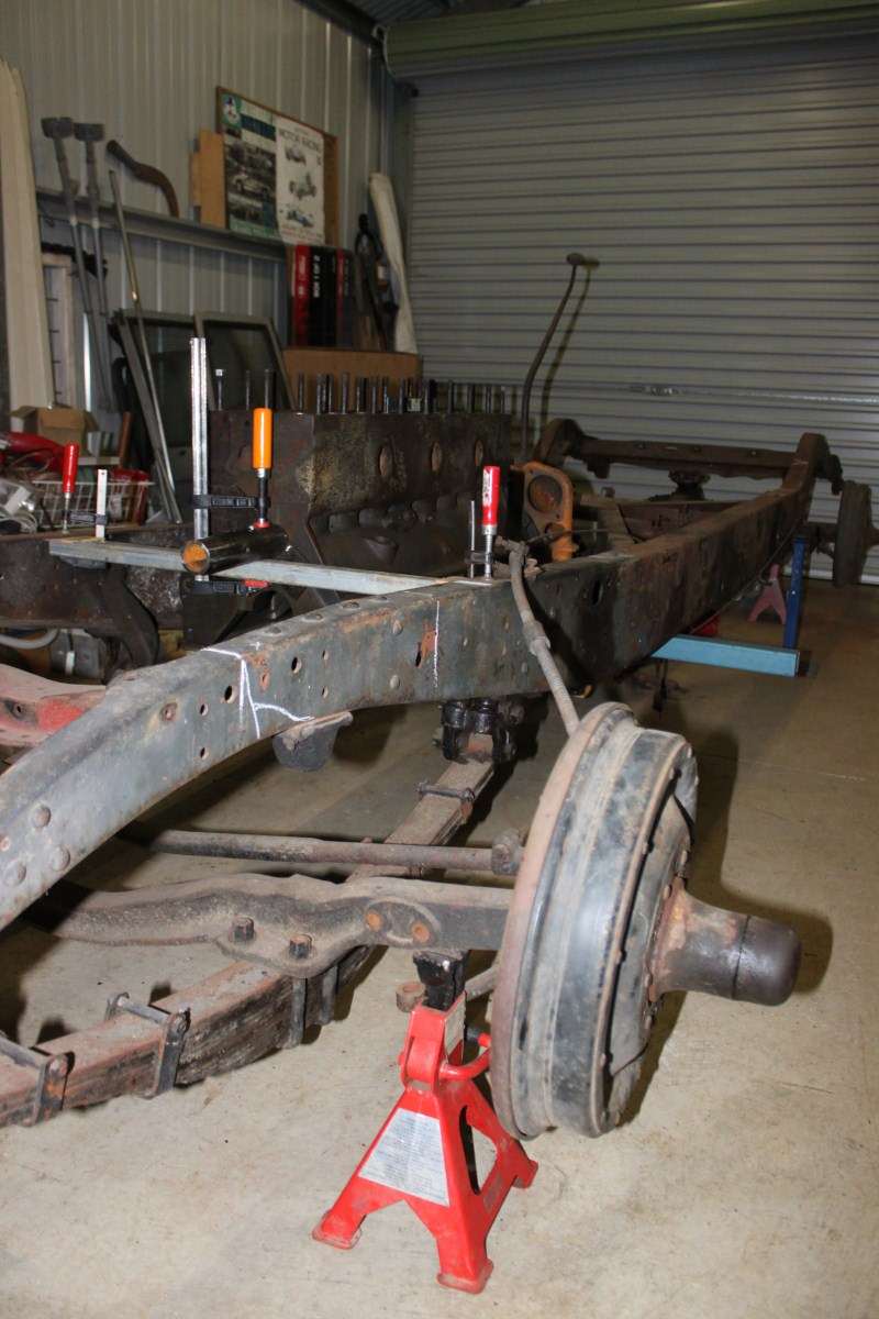 (89.99 KB) (89.99 KB)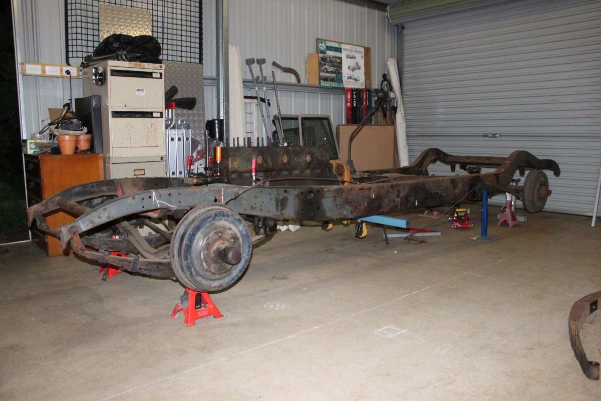 (83.62 KB) (83.62 KB)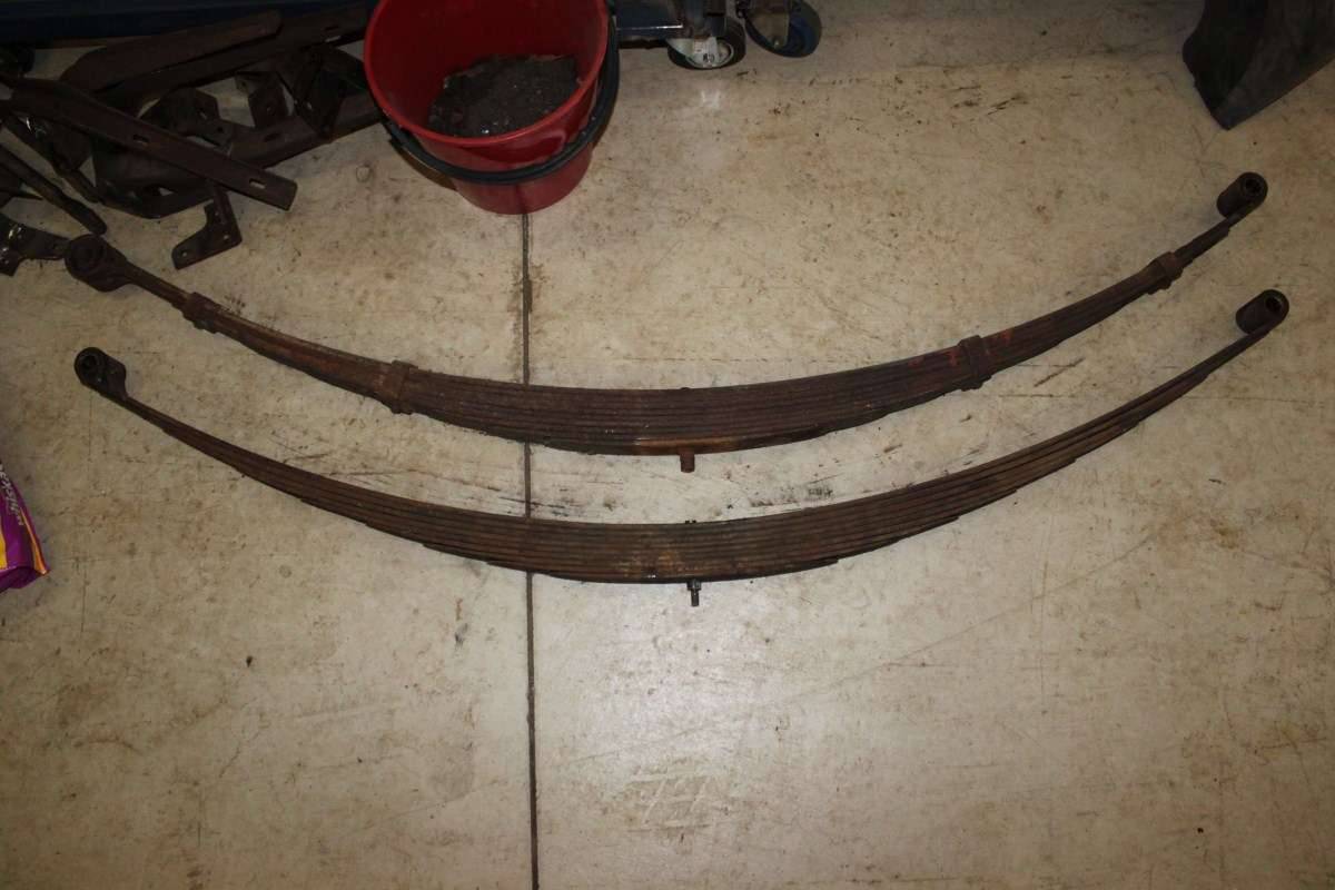 (76.38 KB) (76.38 KB)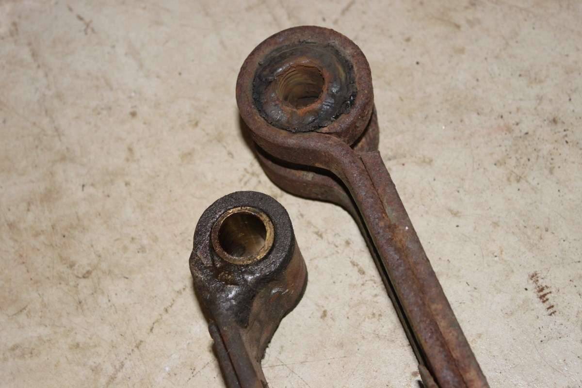 (110.92 KB) (110.92 KB)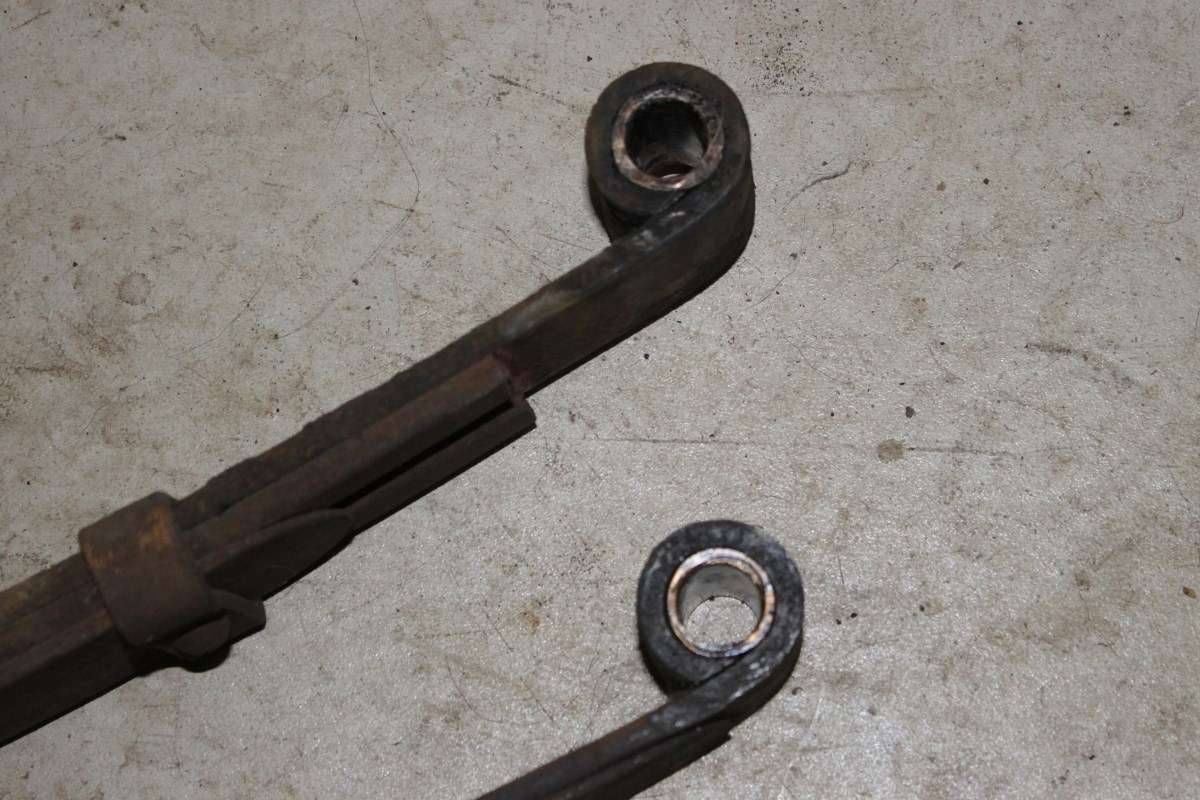 (96.60 KB) (96.60 KB)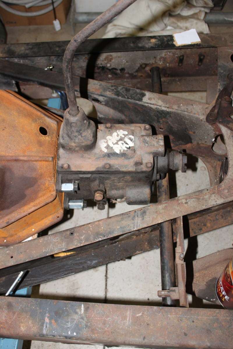 (84.34 KB) (84.34 KB)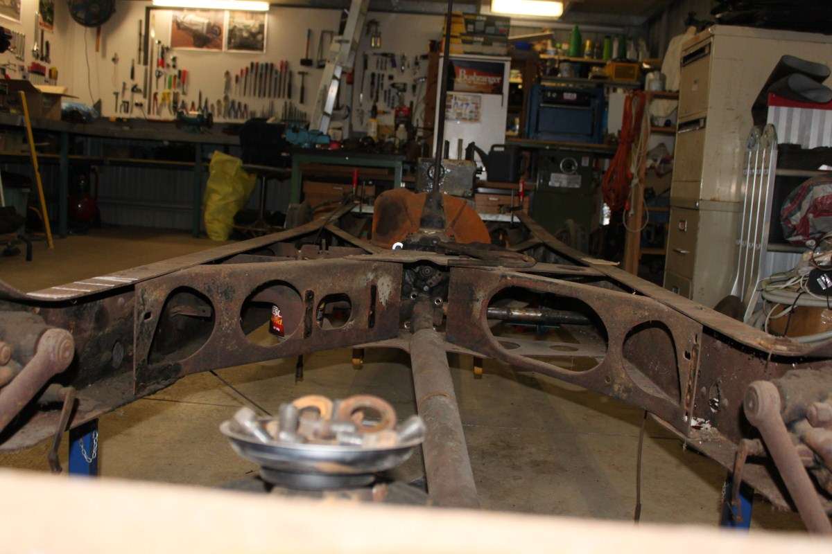 (96.91 KB) (96.91 KB)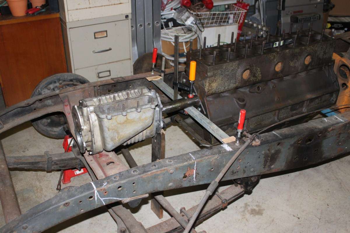 (90.09 KB) (90.09 KB)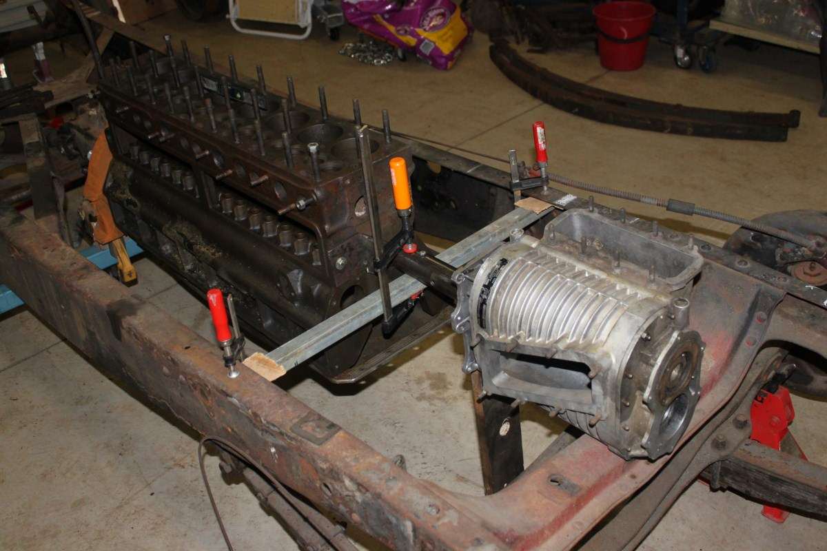
Posted on: 2011/6/27 5:16
|
|||
|
If at First You Don't Succeed - Skydiving is Not For You...
|
||||
|
||||
|
Re: Snapey's 1935 Racing Biposto
|
||||
|---|---|---|---|---|
|
Home away from home
|
Back to earth now, I can see where your cut lines will leave the blower. Looks very doable, and it will definitely be crazy enough without building a 2-cycle, 4-cam, 16-cylinder. Those eight little cylinders should do more than enough.
Consider the builder who did the most with the least: Miller and his 4-cylinder intercooled turbo, one of the slickest designs ever. What was that again, something like 91 cid? So, I think you've got plenty of displacement, and I will just note once again that as far as breathing is concerned, you'll probably have the manifold pressure to push a lot of air through the valves whether it wants to go through or not. Maybe just add a turbo to be sure? Belt and suspenders? Plenty of hotrods in this country sport blowers and turbos--even twin turbos. Whether these setups actually run or not--or just serve as underhood ornamentation--I've never been able to determine.
Posted on: 2011/6/27 19:39
|
|||
|
Guy
[b]Not an Expert[/ |
||||
|
||||
|
Re: Snapey's 1935 Racing Biposto
|
||||
|---|---|---|---|---|
|
Home away from home
|
So, last weekend was busy with other things happening, but I did get to spend some very productive time on the Biposto project between everything else.
The goal was to clean up (read remove as much weight as possible from) the rear of the chassis, establish a good solid centre line standard for measuring and then start the chassis modifications with narrowing the rear end. In standard form the distance across the rear of the chassis is about 45" with the chassis rails essentially tapering uniformly from rear to front where they measure about 28.5" (as you can see in some of the earlier photos). My objective was to cut the chassis C-section flanges top and bottom starting from just behind the end of the crucifix on each side and then pull the rails inwards a little at a time. I did some basic calculations which showed that with a cut of about 1/16" I should be able to get about 1.5-1" movement inwards for each rail. These calcs told me that I would probably need around 10 cuts to do the job and looking at the chassis I decided to make them at 2" intervals. I even went so far to draw up the curve that would be produced and plotted it out at full 1:1 scale - the piece of paper is over 7ft long! The curve looked great so we proceeded with the plans of a 1/16" cut every 2". The drawing I made could also be used to guide the curve if needed, but this didn't end up being required. By the way - just to let you know that I do most of my work in millimetres, but most people understand inches and my father reckoned it was only fitting to use imperial measurements when dealing with "a big Yankee truck" (his words, not mine!) like the '34. So all the rivets were ground, drilled and punched out (a big job in itself) and the two rear cross members removed along with the forged steel spring hanger eyes. These steel forgings will most likely be recycled and used on the front of the car, where their different offset should work well to counteract the 'widening' of the hanging points when the tapered chassis rails are cut about 15" shorter at the front. Removal of the cross members left space for putting though a centre beam to give me something to measure off, so 2 pieces of 2x1" RHS were welded across the top of the chassis to fix this to. A length of 1" aluminium square section was then clamped to these to mark the centreline of the car so I could measure off it as the modification progressed. This would get in the way a bit but was the only way to make the changes accurately. The first cut, as you can see in the first 2 photos, was made right next to the ends of the crucifix. I made this using a wider 1/8" disc in the little 4" grinder, but this proved excessive and just made more work when it came to welding, but it did allow me to take a bit bigger bite to start the process, so the initial change to each rail was more like 2" each side (4" overall). A length of threaded rod was pushed through two existing holes on opposite sides of the chassis and this with a couple of nuts and washers was used to pull and hold the chassis rails in as the work progressed. 1-Cut top and bottom flanges on both sides, 2-pull in, 3-measure, 4-adjust, 5-measure, 6-measure again, 7-tack weld one side top and bottom, 8-measure, 9-adjust, 10-measure, 11-measure again, 12-tack weld other side top and bottom, 13-then cut again 2" further along and start the process over... 9 times!!!! My back is still sore and I now understand why the professionals spend thousands on chassis jigs and rotisseries! After the first set of cuts I changed to the thin kerf 1mm cutting discs and these really are great things to have around! The cuts are quicker and cleaner and you make less mess by removing less material... hmmm - note to self - must remember to put some more on the shopping list... One of the tricks I found that seems to work is taking account of shrinkage after a weld is made. As the weld cools it shrinks and this can (and often does) cause distortion in the job. But measuring before each weld was made I was able to weld the side that needed to move in the most first each time, then adjust the pull on the other side to match it and allow a little for shrinkage there as well and it worked out very well indeed - even if I do say so myself (which - quite obviously - I do). Especially when you consider that yours truly is a rank amateur at these things. The end result of all this is that the width across the rear end of the chassis is now closer to 22" instead of 45" - which is pretty much exactly what I wanted. Two things surprised me when I first removed the two rear cross members from the chassis rails. The first was how much strain they had been under. When I finally removed the last rivet that was holding it all together the whole thing kinda went 'sproing'! Not enough to throw things in the air, you understand, but enough to make me move my hand out of the way very quickly when I saw it coming. I can only think that since there is no sign of repair to the chassis itself that these forces have been stored in that metal for almost 80years... beat that Mr Eveready! I almost wish I had gained a scar from it so that it did not pass unrecorded - but I suppose that is what I am doing by writing it all down here isn't it? The second thing that surprised me was just how much ridgity they add to the rear of the chassis. Without these in place I could just tap the end of one chassis rail and it would wobble all over the place. I could grab the end of each rail and twist them 5 or 10 degrees either way just with my hand. Even up and down the amount of movement is quite pronounced, especially given the size & depth of the chassis rails. "Hmmm" I thought to myself... " I will probably need to fix that..." Keeping the amount of tension or pre-existing distortion in mind then, should I have expected it to be easy to put the first of these two cross members back into position once the cutting and welding of the rails was completed? Probably not, but I did. The rear most piece that joins the very rear ends of the rails together is to be replaced with two lengths of DOM tube which will cantilever the rear ends of the rear spring packs, and it was somewhat out of shape anyway, so it ended up on the 'Jenny Craig Pile'. This is where all the steel removed from the car is being placed so that I can weigh it at the end of the project. The cross member that was second from the rear, which I think the fuel tank would have been strapped to, was then cleaned up with the steel cup brush on the 4" grinder, measured, marked, cut and checked for fit. G clamps and vice grips were used to pull it all back into alignment while it was welded into place. There was some head scratching and grunting involved, but hopefully the energy that I put into it all will go 'sproing' and catch some other poor fool by surprise if they ever decide to cut up my hard work! Given the change in geometry that had taken place this was a little bit tedious, but I'm very happy with the result - an original (but lighter) piece of steel back in close to its original position and serving its original purpose very well. Bit of a shame that no one will ever see it really... Now some of you may be looking at some of these photos thinking it all looks too narrow to retain the stiffness that would be required, but remember that the car will end up weighing (hopefully) less than half of its original weight and that only a fraction of that will be placed on the rear most spring hangers. Also, to comply with local competition regulations the car will need to be fitted with a roll bar, and I plan to brace this back to the tail and triangulate the structure and so stiffen up the rear of the car substantially. As well as all this I also (with the help of my beautiful and long suffering wife) pulled the rear diff out of the way and placed it on blocks to one side. My next job here will be to use the hydraulic puller that I have borrowed from my father to pop the rear hubs off the axles to examine the rear brakes, seals and bearings. If it all looks OK I will probably just put it back together and see how it goes. I have already removed the front hubs and drums and found that everything seemed to be in very good condition - even the brake shoes look serviceable with plenty of meat on them. Certainly enough for the initial test runs which will be done on a closed race circuit. Also, I pulled the rear spring packs apart to see what could be made of them. I will certainly need the two new main leaves as previously mentioned, but by using one of the old main leaves to make a new second leaf and then removing, switching and modifying the rest of the pack I might be able to get away with minimal cost. I still have to clean them all up properly though (more work for the little grinder) so we will see what can be done. I will also look at using new packs if I can find something locally that will fit. Once again I will leave that up to my local spring guys - they are very good at what they do. Finally, on Sunday, I jacked up the front of the car and placed jack stands under the chassis in preparation of removal of the front axle and then cutting off the front of the chassis rails. I then poured myself a large glass of red wine and sat and looked at it for a while. This next part is going to be a pretty big job, as putting the front spring points where they will be required is going to require quite a lot of detailed fabrication work - sounds like fun, don't you think? Attach file: (58.81 KB)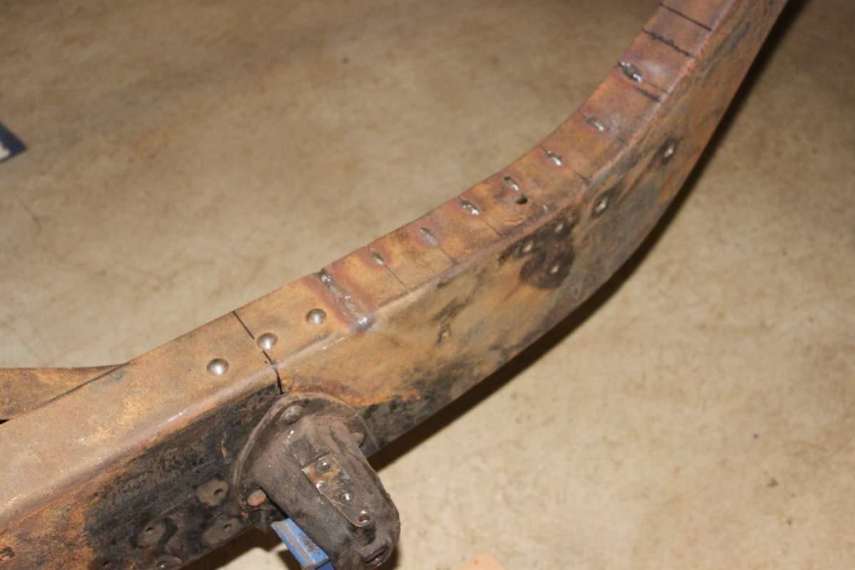 (83.09 KB) (83.09 KB)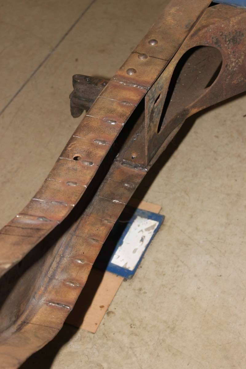 (89.27 KB) (89.27 KB)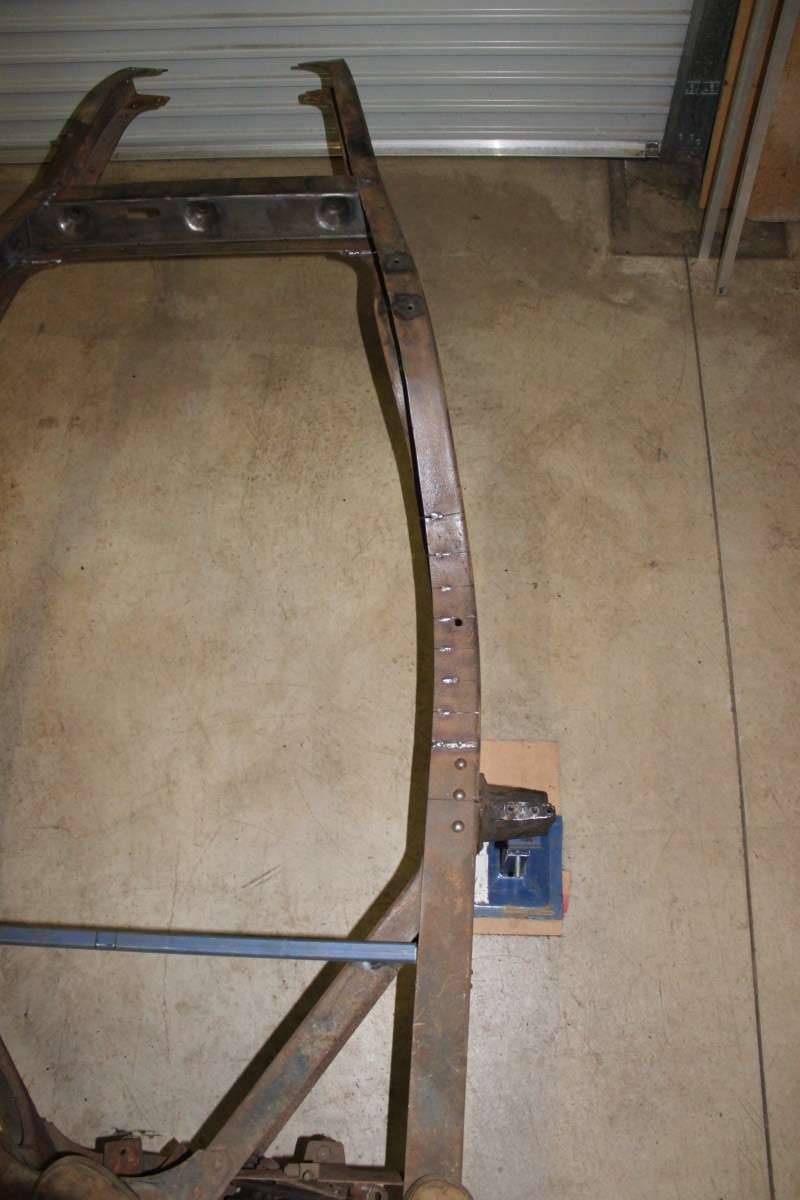 (92.71 KB) (92.71 KB)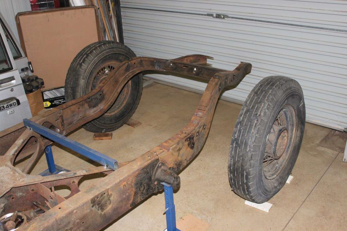 (97.40 KB) (97.40 KB)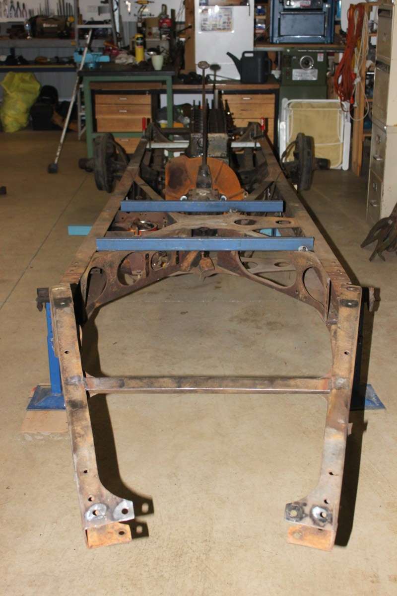 (85.11 KB) (85.11 KB)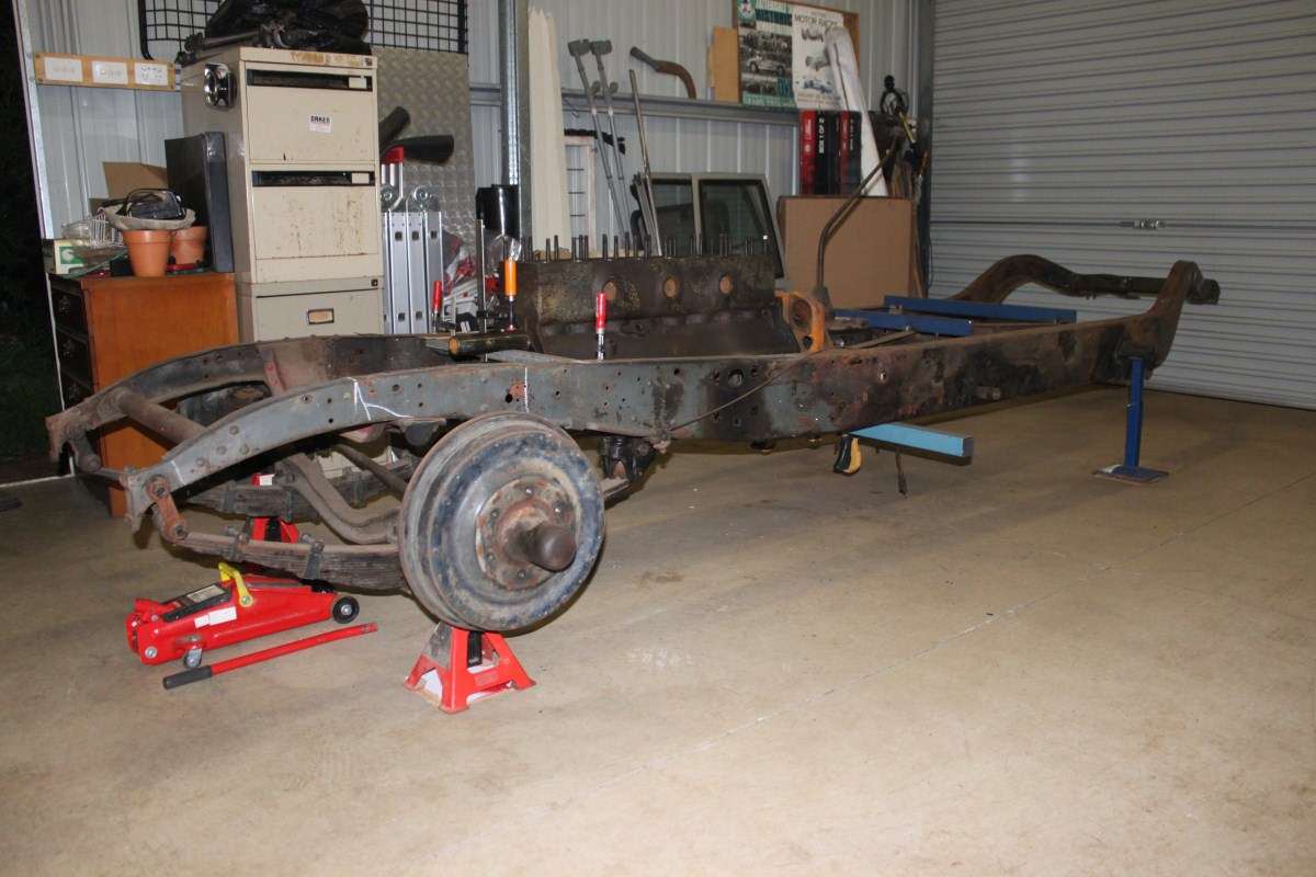 (101.79 KB) (101.79 KB)
Posted on: 2011/7/4 6:43
|
|||
|
If at First You Don't Succeed - Skydiving is Not For You...
|
||||
|
||||


