|
Re: Location of the Brake pedal adjustment??
|
||||
|---|---|---|---|---|
|
Forum Ambassador
|
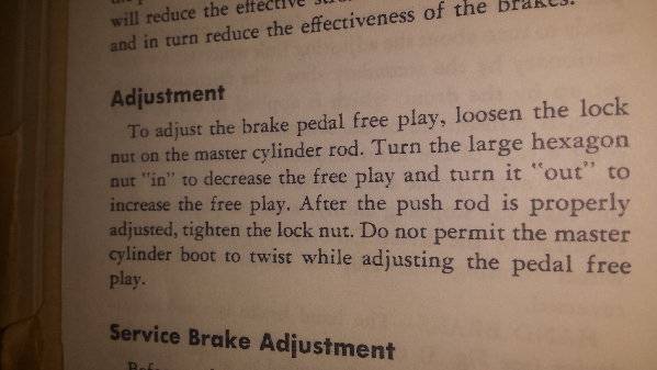
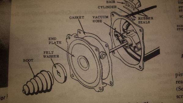
The adjustment procedure is for manual brakes and the illustration of the brake unit is the power brake. There is no free play adjustment for Packard power brakes using the Bendix TreadleVac unit. Any free pedal movement is built into the unit and is the distance the valve moves before it can open and control the vacuum applied to the power piston. Everything in the booster unit is directly fastened together and a very large spring in the booster returns the pedal, valve, power piston and master cylinder ram to their resting place and ensures the brakes stay released when at rest.
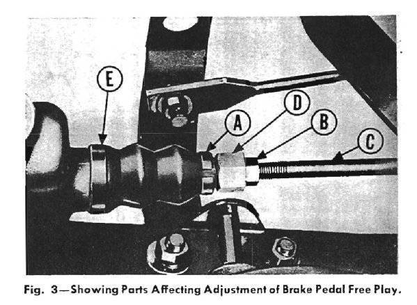
For the manual brakes, because of different springs, linkage, and overall geometry some free play is needed. There is a rod attached to a welded on pin at the bottom of the brake pedal arm. That rod extends toward the master cylinder. On the end at the master side is a piece that pushes against the piston in the master cylinder. The piece threads onto the rod and is turned to make the adjustment. The locking nut which is described in the procedure, when tightened pushes against the adjustment piece to lock them together so the adjustment piece will not unscrew. In the illustration that would be appropriate to the procedure described the rod attached to pedal arm is C, nut they have you loosen is B, and the part to turn to adjust is D. The illustration is out of the 46-50 SM and is appropriate for all models with manual brakes but the location of the master cylinder and actual look of the parts may vary slightly by year or model.
Posted on: 2019/5/4 12:48
|
|||
|
Howard
|
||||
|
||||

Hello and welcome to Packard Motor Car Information! If you're new here, please register for a free account.
 (129.27 KB)