
|
Re: INSTRUMENT VOLTAGE REGULATOR (55th Series Clipper)
|
||||
|---|---|---|---|---|
|
Forum Ambassador

|
The 55 instrument regulator supplies a pulsing on and off 12v out to the gauges and when you factor in the on and off times of the pulses results in an average value of 5v feeding them. Because of the pulsing the typical VOM most people use will not have the ability to provide the 5v number. The readout will instead just jump up and down and depending on the speed of the pulses and whatever delays in the meter while it calculates and displays you may see a number anywhere in the range from 0 to 12v.
About the best you can do is connect 12v to the battery input on the regulator and ground to the cluster. Verify some voltage is being fed to the gauges. You do not want to see a solid 12v nor do you want to see a constant 0v. The regulator needs to be grounded to be able to operate and if there is a solid 12v or 0v out the regulator is not working. With the gauges powered, you should be able to ground the sender side terminal and have the gauges go to full scale. Use caution and just check that the gauges move and do not leave them grounded longer than needed. With a solid ground connection for too long there is a possibility the gauge could burn out. The gauges have heaters wrapped around bimetal strips which move the needles. Those are heated proportionally via the feedback of the changing resistance in the senders. Because of the relative slowness of the heating action on the bimetal strips in the gauges the 12v pulses are not seen and the needles remain steady and constant. Here is a photo showing the typical output of the stock regulator and what it looks like inside as well as the inside of a gauge. During this test there were 3 gauges attached but on Clippers with only 2 gauges running off the regulator the load and waveform will be slightly different. Attach file:  Instrument Regulator output waveform.jpg (44.64 KB) Instrument Regulator output waveform.jpg (44.64 KB)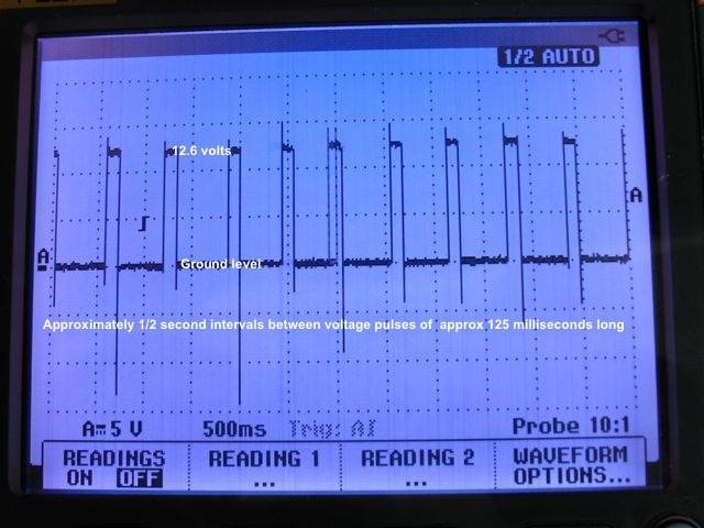  IMG_0266.jpeg (69.84 KB) IMG_0266.jpeg (69.84 KB)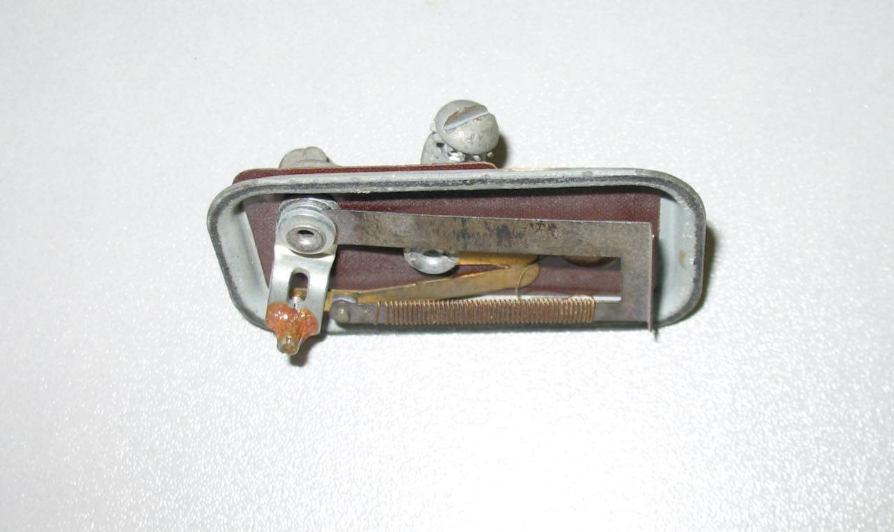 IMG_0159.jpeg (121.72 KB) IMG_0159.jpeg (121.72 KB)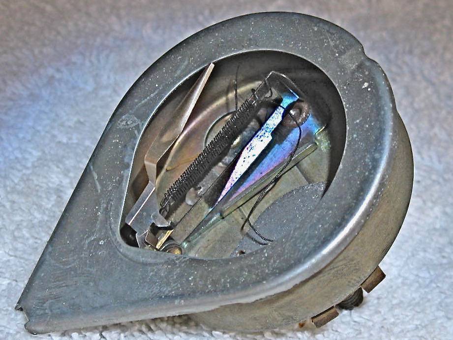
Posted on: 2021/11/11 17:39
|
|||
|
Howard
|
||||
|
||||
Happy 4th of July and welcome to Packard Motor Car Information! If you're new here, please register for a free account.


