Hello and welcome to Packard Motor Car Information! If you're new here, please register for a free account.  
Login
Username:

Password:

Remember me


Lost Password?

Register now!
FAQ's
Main Menu
Recent Forum Topics
Who is Online
121 user(s) are online (81 user(s) are browsing Forums)

Members: 0
Guests: 121

more...
Helping out...
PackardInfo is a free resource for Packard Owners that is completely supported by user donations. If you can help out, that would be great!

Donate via PayPal
Video Content
Visit PackardInfo.com YouTube Playlist

Donate via PayPal


(1) 2 3 4 ... 7 »

DIY Torsion level control switch conversion
#1
Forum Ambassador
Forum Ambassador

HH56
See User information
If the switch fails, here is one way to eliminate the bimetal timing section and sometimes erratic contacts in the stock control switches by adding solid state time delay relays. No idea which vendors are selling the exchange switches so here is an option if an owner wants to do a conversion himself. Different relays may work better or not at all but I chose these because they were fairly inexpensive and readily available.

The relays I used are by INITEQ number INRXTD12X30B and are currently sold as a pair by Amazon. These are 12v 30 amp contact automotive type relays. Some Ebay vendors also sell a similar relay. Riki shows another brand in one of his posts. Space is extremely tight inside the control sw box. The INITEQ relays are 1 1/8” square x 1 15/16“ long. The flag terminal brings total length to 2 1/4”. Any larger relay may not fit and not sure if there would need to be any mods to the mounting bracket showing on the type relay Riki purchased. The easily found TD relays all seem to have a delay of 10 seconds which is longer than the factory specified 5-7 second delay but still a reasonable number.

First step was to unsolder 4 wires and unscrew the old relay bracket to remove the complete relay assy.

I could not find a way to avoid cutting the bimetal strips out of the box and still have the relays fit. A Dremel with cut-off wheel was used to cut the bimetal assy off the swivel bracket just as is done with the other solid state conversions. A couple of the old contacts were bent out of the way on the phenolic circuit board at the bottom to make room for the new support plate but nothing else needed cutting.

A hole was drilled in the pot metal for a new ground stud connection and two new wires were soldered to the existing pink and yellow terminals going to the outside. NOTE: Because the terminals have a large mass you will need a fairly high wattage soldering iron for this —at least 200 watts. New wires were also soldered back onto the terminals connected to the contacts operated by the lever and torsion bar. A regular wattage soldering iron will work for those. Because space is so tight I chose to use insulated flag style quick disconnects to connect the relays but those do need a special crimper. Another option would be to solder wires directly to the relays. If you do that make sure not to overheat the relay terminals and carefully insulate the terminals after the wires are on so they can not touch the cover.

A plate was also made to support the relays above the still existing contacts on the switch bottom. I chose to use a 1/16 thick phenolic material with dimensions of 1 7/8 x 2 1/8. Holes were drilled and countersunk in the plate to utilize the old relay bracket screw mounting location and threaded holes. The plate was placed on 1/2" standoffs using 3/4" screws. Note that the original relay bracket screws in the switch are an odd size -- 5-40 thread. That size is available but not typically found at local hardware stores. You could use easier to find 4-40 screws thru the original holes with a nut under the box to hold the screws or drill and tap the holes for 6-32.

IF you have a 55 switch, electrically they are the same with the main difference being the location of the terminals on the bottom. 55 switches had 3 exposed screw terminals and they are in different spots. Pink and Yellow wires would need to go to the different terminal locations.

Here are a few photos of a 56 switch as well as the new wiring diagram. NOTE: The wiring diagram is for the 56 Negative ground switch conversion. Wires 85 and 86 on each relay would need to be swapped for the 55 Positive ground. Both configurations test well on a bench but I will not be able to crawl under to test the conversion in a car.

Attach file:


jpg  TL 1.jpg (186.49 KB)
209_6445e56e5237e.jpg 1200X998 px

jpg  TL 2.jpg (139.18 KB)
209_6445e57ba9f67.jpg 1200X958 px

jpg  56TorSwitch1 2.jpg (168.79 KB)
209_6445e58bc9bd0.jpg 1769X1208 px

Posted on: 2023/4/23 21:21
Howard
 Top  Print   
Like (1)


Re: DIY Torsion level control switch conversion
#2
Home away from home
Home away from home

R H
See User information
Send one to me h.

I will try it

Posted on: 2023/4/23 22:55
Riki
 Top  Print   


Re: DIY Torsion level control switch conversion
#3
Home away from home
Home away from home

R H
See User information
The pivot contacts. I was thinking of removing those and put in micro switches.

I think those contacts can act up to.

Posted on: 2023/4/23 23:02
Riki
 Top  Print   


Re: DIY Torsion level control switch conversion
#4
Just can't stay away

5540Packards
See User information
When I first got my 55 I had a few issues with the torsion level I had the original control box replaced with a solid state control box from Pacific Northwest Packards . I sent them the original control box and they put the modern electronics in. PROBLEM SOLVED never had an issue with it after that.

Posted on: 2023/4/23 23:40
 Top  Print   


Re: DIY Torsion level control switch conversion
#5
Forum Ambassador
Forum Ambassador

HH56
See User information
The exchange boxes are a good product and for those not mechanically inclined or those wanting to do a quick swap, well worth getting. Problem for anyone needing one is the project page no longer appears to be on the PNW website. No idea if they still offer them and if not, who does. Some also like to do their own work and by using available relays it makes the job possible and much less expensive.

Posted on: 2023/4/24 0:10
Howard
 Top  Print   


Re: DIY Torsion level control switch conversion
#6
Home away from home
Home away from home

R H
See User information
They don't use yours

They exchange.

Posted on: 2023/4/24 5:51
Riki
 Top  Print   


Re: DIY Torsion level control switch conversion
#7
Forum Ambassador
Forum Ambassador

HH56
See User information
Quote:

R H wrote:
The pivot contacts. I was thinking of removing those and put in micro switches.

I think those contacts can act up to.

Those contacts do get dirty and can act up. A microswitch conversion is not a bad idea and I have just the candidate in a box that has a broken spring and for whatever reason it happened, a broken off center piece for the pivot contact.

Have not figured out how to get the pivot off to change the torsion spring but can play around with what is still there to work out places to mount a pair of microswitches and have them activate. Am thinking switches like you used in your PB assy would probably fit.

Posted on: 2023/4/24 9:13
Howard
 Top  Print   


Re: DIY Torsion level control switch conversion
#8
Home away from home
Home away from home

CarFreak
See User information
Quote:

HH56 wrote:
If the switch fails, here is one way to eliminate the bimetal timing section and sometimes erratic contacts in the stock control switches by adding solid state time delay relays. No idea which vendors are selling the exchange switches so here is an option if an owner wants to do a conversion himself. Different relays may work better or not at all but I chose these because they were fairly inexpensive and readily available.

The relays I used are by INITEQ number INRXTD12X30B and are currently sold as a pair by Amazon. These are 12v 30 amp contact automotive type relays. Some Ebay vendors also sell a similar relay. Riki shows another brand in one of his posts. Space is extremely tight inside the control sw box. The INITEQ relays are 1 1/8” square x 1 15/16“ long. The flag terminal brings total length to 2 1/4”. Any larger relay may not fit and not sure if there would need to be any mods to the mounting bracket showing on the type relay Riki purchased. The easily found TD relays all seem to have a delay of 10 seconds which is longer than the factory specified 5-7 second delay but still a reasonable number.

First step was to unsolder 4 wires and unscrew the old relay bracket to remove the complete relay assy.

I could not find a way to avoid cutting the bimetal strips out of the box and still have the relays fit. A Dremel with cut-off wheel was used to cut the bimetal assy off the swivel bracket just as is done with the other solid state conversions. A couple of the old contacts were bent out of the way on the phenolic circuit board at the bottom to make room for the new support plate but nothing else needed cutting.

A hole was drilled in the pot metal for a new ground stud connection and two new wires were soldered to the existing pink and yellow terminals going to the outside. NOTE: Because the terminals have a large mass you will need a fairly high wattage soldering iron for this —at least 200 watts. New wires were also soldered back onto the terminals connected to the contacts operated by the lever and torsion bar. A regular wattage soldering iron will work for those. Because space is so tight I chose to use insulated flag style quick disconnects to connect the relays but those do need a special crimper. Another option would be to solder wires directly to the relays. If you do that make sure not to overheat the relay terminals and carefully insulate the terminals after the wires are on so they can not touch the cover.

A plate was also made to support the relays above the still existing contacts on the switch bottom. I chose to use a 1/16 thick phenolic material with dimensions of 1 7/8 x 2 1/8. Holes were drilled and countersunk in the plate to utilize the old relay bracket screw mounting location and threaded holes. The plate was placed on 1/2" standoffs using 3/4" screws. Note that the original relay bracket screws in the switch are an odd size -- 5-40 thread. That size is available but not typically found at local hardware stores. You could use easier to find 4-40 screws thru the original holes with a nut under the box to hold the screws or drill and tap the holes for 6-32.

IF you have a 55 switch, electrically they are the same with the main difference being the location of the terminals on the bottom. 55 switches had 3 exposed screw terminals and they are in different spots. Pink and Yellow wires would need to go to the different terminal locations.

Here are a few photos of a 56 switch as well as the new wiring diagram. NOTE: The wiring diagram is for the 56 Negative ground switch conversion. Wires 85 and 86 on each relay would need to be swapped for the 55 Positive ground. Both configurations test well on a bench but I will not be able to crawl under to test the conversion in a car.


Thank you so much for this!! this is amazing!!

when I finish maintenance up on my truck I will try this mod!!

Posted on: 2023/4/24 12:45
 Top  Print   


Re: DIY Torsion level control switch conversion
#9
Home away from home
Home away from home

R H
See User information
H.

What about this.

Didnt see pin layout. Is expensive. But adjustable.


https://m.delcity.net/store/Time-Delay-Relays/p_804415.h_804416

Posted on: 2023/4/25 8:38
Riki
 Top  Print   


Re: DIY Torsion level control switch conversion
#10
Forum Ambassador
Forum Ambassador

HH56
See User information
Riki, Pinout is the same but I don't know if the relay would work because of one definite statement on the info sheet where it says power must be present on pin 30 for the relay to cycle. We use a ground at that terminal. With the statement and wording I suspect they are taking a constant power for the timer electronics from that terminal and pin 86 just needs a momentary signal. Would almost need to test a relay to see what or how it does.

There is a similar pin description but not the same must have or it won't work statement for the relay I used. I can confirm the Amazon relays do operate the solenoids on the bench but cannot confirm any extraneous noise found in the car would not affect the relay operation. Since the Amazon relays claim to be automotive relays would doubt that would be an issue but since modern cars are much better shielded than 70 year old Packards that still needs to be confirmed.

Another question needing an answer would be the dimensions since it cannot be any larger than what I measured on the Amazon relay to have two relays fit in the box.

Price wise if they would work, instead of $22 for a pair it would be about $54 for the pair. Might be worth it for the adjustable feature to get the factory spec and to have German made quality instead of Chinese made.

Attach file:


jpg  relay.jpg (118.75 KB)
209_6447ee4bf25e8.jpg 1920X1403 px

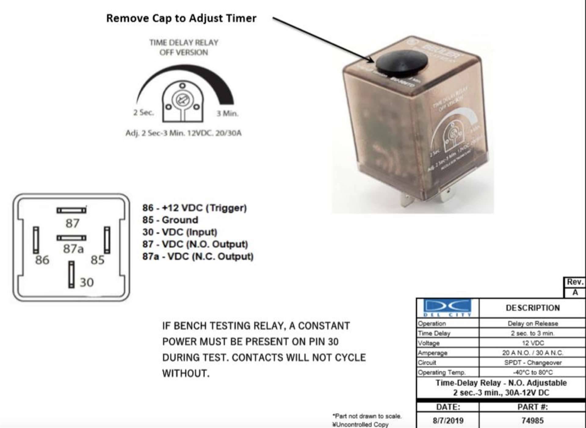
Posted on: 2023/4/25 10:15
Howard
 Top  Print   


(1) 2 3 4 ... 7 »


Search
Recent Photos
Photo of the Day
Recent Registry
Website Comments or Questions?? Click Here Copyright 2006-2024, PackardInfo.com All Rights Reserved