
|
Re: Continuing on the Overdrive
|
||||
|---|---|---|---|---|
|
Home away from home
|
Here is the latest update:
First - no modification for safety switch in reverse. I grounded the governor and tested for continuity at terminals 3 and 4. I have a light at both terminals! When I contacted terminal 4 with my tester, the solenoid engaged. It did not stay out, but engaged several times. It did not machine gun, and the engagement was intermittent, almost like you would tap the starter with the ignition switch. The wire at the terminal is tight, but I did not remove the wires and clean the connections. Everything is quite clean in the area. This might be another clue: I have a kill switch in the general area of the relay, so when I hooked up the ground to the governor, I had the juice off. I then turned on the kill switch to start my test. When I turned on the power, I noted a very quiet hissing sound (really sounded like an air hose leak) coming from the relay. The cover was on at the time so I could not identify the source. As soon as I contacted #4 terminal with my light, the sound stopped, and within a second or two, the solenoid engaged. The sound did not return. I did all testing with the ignition off. (Why does THAT work?) There may be something unusual about my relay: In the manual, terminal #1 is closest to the Actuating Relay (the one with two sets of points) and the Ground Out Relay is closest to terminal #3. My relay is reversed. The Ground Out Relay (one point set only) is closest to terminal #1, and the Actuating Relay (two points sets) is closest to terminal #3. The tops of both relays (where the points are located) are oriented to terminals 1,2 and 3, so this is not somehow just installed upside down. The expected #1 terminal is the always hot terminal. The relay has clearly been worked on with plenty of solder around the terminals inside. (Wish I had taken a picture). I also noticed that, when I would kill the power through the kill switch, the Ground Out Relay points would remain closed until I would manually open them. Since they were engaged at the time I hit the kill switch, maybe this is expected. I did seperately test that the lockout switch and the kickdown switch were both closed as expected. I did not have time to wire directly from #3 and #4 to the respective terminals on the solenoid. Because of the relay set-up, I will first continuity test the wires to make sure I know where everything is going. But the wiring appears to be as shown in the manual. Because I am grounding the governor, I assume the wire from the governor to terminal #5 could also be an issue if bad. Can I simply disconnect the wires from terminal #5 and ground it directly? I am sorry that I don't have a better understanding of the electrical and particularly the relay operation. I am having to get step by step guidance, so i really appreciate the patience that you guys (and particularly HH) have shown. I hope I am providing enough data for those of you who do understand this to be able to make a good diagnosis. I do feel like I am making a lot of progress. It is very hard for me to ignore something that is not working right. This would be a lot more fun if I didn't have to crawl under the car so often. But it is still actually fun and I really feel like I am learning something.
Posted on: 2009/8/27 11:55
|
|||
|
1941 Touring Sedan
1952 250 Convertible 1932 902 Rumble seat Coupe  Who is John Galt? Who is John Galt?
|
||||
|
||||
|
Re: Continuing on the Overdrive
|
||||
|---|---|---|---|---|
|
Forum Ambassador

|
Lets make sure we're talking of same type relay for starts. Here is R9 relay and pict with cover removed and terminals identified. Term 1 is fed directly from battery via starter solenoid post so does not go thru ignition switch. As to why solenoid would energize after touching with your light, if governor grounded and switches & relay functioning properly, term 3 & 4 and solenoid should have already been energized so just lit the test lamp--don't understand the on/off unless there is a bad connection when you push on it.
You can ground terminal 5 directly-just won't have all the circuitry to rule anything out but if you have determined both switches and wires good, then easier than crawling under. When you refer to a kill switch--is that just a battery disconnect in cable from battery? Also, looking at the 41 general schematic it appears yours does use the black connectors and the short loom so worth a look there. Attach file:  (47.24 KB) (47.24 KB)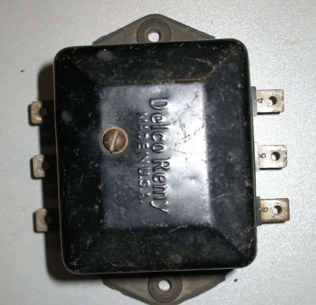 (44.60 KB) (44.60 KB)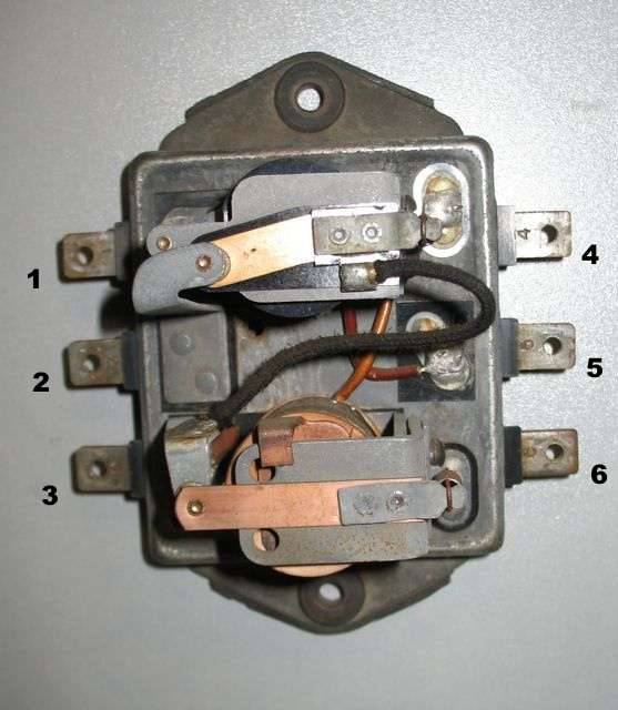
Posted on: 2009/8/27 13:13
|
|||
|
||||
|
Re: Continuing on the Overdrive
|
||||
|---|---|---|---|---|
|
Forum Ambassador
|
Here is a bit more to add to the mix.
R9 Relay operation: There is a bit of description in the manual but maybe this will flesh it out--or confuse issues further. Power is supplied to terminal 1, thru first relay coil & out terminal 5. Thru closed lockout switch, closed kickdown switch and gets ground when car reaches speed. First relay energizes and provides power to term 4, solenoid pull in coil and indicator light. Indicator will light as solenoid still not fully engaged and light contacts are closed. At the same time first relay opens the contacts tied to terminal 2. Power is also supplied to and thru the coil of second relay and out terminal 3 to hold coil. Since they are in series, second relay closes contacts tied to terminal 6 and hold coil now has power and will prevent the machine gunning. When you let off the gas, engine torque is released, and solenoid fully engages. Pull in coil contacts open that circuit. Indicator light contacts open, extinguishing light, but engine kill contacts now close at 6. Engine is not affected though because kill circuit goes thru term 6, closed second relay contacts but no further because first relay contacts are now open so can't exit on term 2 and get to distributor. This is the state of things as long as you are in overdrive. When you exit overdrive via kickdown, that switch opens dropping out first relay and power to solenoid. Solenoid can't release until torque released so kill circuit is now completed by previously open first relay contacts at 2 and engine skips a beat until solenoid drops out and opens that set of kill contacts. Just before it opens the kill contacts it closes pull in coil contacts. The second relay will drop out because it also lost power but because it's coil is now in series with pull in coil & hold coil, will have a slight delay of a few milliseconds until everything quiets down. There is a bit of a race as to which contacts opens first but once open it ensures kill circuit is open in case of a bind at solenoid and engine can continue running. When OD is in lockout, nothing can be energized when governor reaches speed because ground never reaches relay. Attach file: (61.80 KB)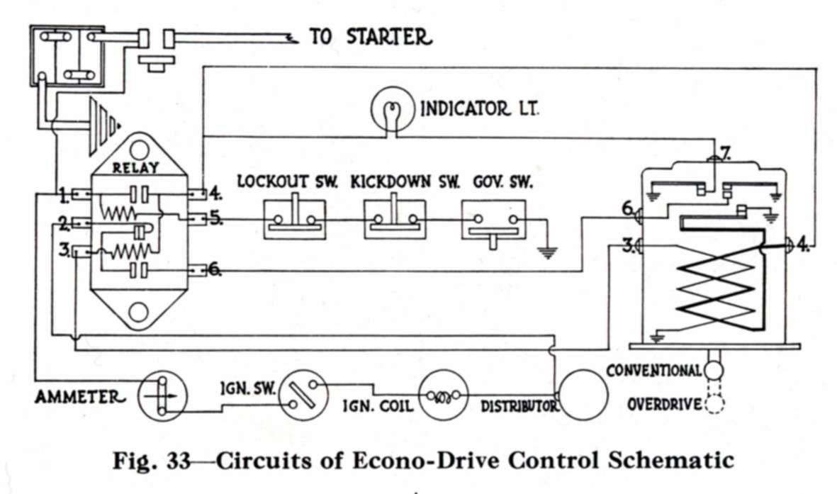
Posted on: 2009/8/27 14:33
|
|||
|
||||
|
Re: Continuing on the Overdrive
|
||||
|---|---|---|---|---|
|
Home away from home
|
We are talking the same relay, but slightly different schematics. I am looking at page 7 of the Econo-Drive Serviceman's training booklet (I attached that page just for easier reference).
Apparently in that schematic, the orientation is from the back of the relay. This makes everything make SOME sense, except that, in this case, when looking at the relay on the firewall, #1 terminal is at the upper left position. That would mean that the terminal that is always powered (always turns on my light) is terminal three, which I have been assuming to be terminal #1. Had I removed some wires, I might have seen the terminals are numbered. This does clear up my earlier comment about the placement of the relays vs. the terminals, but now I am really confused as what I think I am seeing must be impossible, because it appears that the #3 terminal in the only one that constantly will light my tester. It also means contacting the #6 terminal is making my solenoid actuate. I think I will need to trace down the wires end to end to understand this better. The kill switch that I am talking about is just a devise that disconnects the negative cable before the starter. I never use it because I have no drain when the car is parked, but I have been using it for this purpose to avoid working underneath with a bunch of hot wires and to avoid energizing my system too long jumping across the governor. Of course, since that has mostly not worked, it hasn't really been an issue. Now I am feeling pretty stupid. I am going back to re-look at everything. Attach file:  Size: 609.21 KB; Hits: 34 Size: 609.21 KB; Hits: 34
Posted on: 2009/8/27 17:07
|
|||
|
1941 Touring Sedan
1952 250 Convertible 1932 902 Rumble seat Coupe Who is John Galt?
|
||||
|
||||
|
Re: Continuing on the Overdrive
|
||||
|---|---|---|---|---|
|
Home away from home
|
Ok. I AM an idiot!
The "power" at what is now correctly identified as terminal 3 was because I had my light set on continuity. I am looking at the wiring diagram and can not see why I should get continuity to ground at terminal three. I also tested this earlier with the solenoid out of the car and still got continuity. I am suspecting this means that I have a short to ground in that wire. That might also be why I was getting the machine gunning effect before the OD died altogether. Voltage meter shows 6 volts to terminal 1 and to terminal 5, not grounding the governer. In grounding directly to Terminal 5 instead of the governor, the solenoid popped out and stayed out. When I tried to use my volt meter to check voltage, contacting #4 terminal caused it to click in and out. I actually think it may have to do with the movement of the relay. Is the relay supposed to be grounded or float above the firewall? I get a lot of movement and I think it may either be contacting the firewall or maybe causing one of the wires to short. Anyway, it looks a lot like a wiring problem, so will start working that angle tonight. I appreciate the explanation of the sequenciing of the electrical system for the OD. I have read this several times in the manual, but your explanation is much more understandble.
Posted on: 2009/8/27 19:00
|
|||
|
1941 Touring Sedan
1952 250 Convertible 1932 902 Rumble seat Coupe Who is John Galt?
|
||||
|
||||
|
Re: Continuing on the Overdrive
|
||||
|---|---|---|---|---|
|
Forum Ambassador

|
Howard, Thank you for all this. That is the best explanation of how the R-9 system works that I have ever read although it took me several readings to digest and understand it. My curiosity is aroused now as to why the green indicator light on my 47 stays on whenever the solenoid is energized. It does not go out when the solenoid is fully engaged. I didn't know that the light was supposed to go out at this point?
Posted on: 2009/8/27 19:32
|
|||
|
||||
|
Re: Continuing on the Overdrive
|
||||
|---|---|---|---|---|
|
Forum Ambassador
|
Relay should not be grounded and is mounted on vibration pads so everything should be at least 3/8 inch away from metal. Sounds as if relay is working at least. The continuity question depends on how things were connected when you made the test so can't hazard a guess but if solenoid totally disconnected and out then that pretty much leads to wiring or motion as you mention. This is a bottom and side shot of the relay so you can tell if yours might be too close to firewall.
Attach file: (25.21 KB)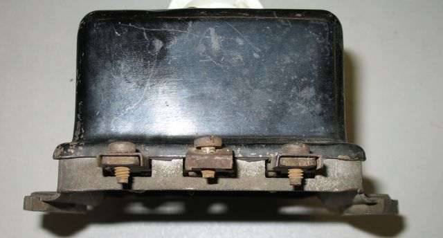 (37.54 KB) (37.54 KB)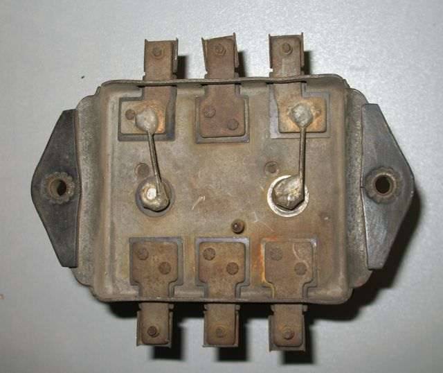
Posted on: 2009/8/27 19:32
|
|||
|
||||
|
Re: Continuing on the Overdrive
|
||||
|---|---|---|---|---|
|
Forum Ambassador
|
Clipper 47. Thanks and glad it was understandable.
The operation of the light is supposed to be as soon as speed is reached and OD is possible it illuminates and stays illuminated until you are in OD and the solenoid has fully engaged. There are a set of contacts in solenoid that then open and light goes out. If you kickdown out of OD but are still above speed, light will go on again as contacts close to tell you that it is still possible to go into OD. If yours is not doing that then probably the contacts have worn out of adjustment or the wire to solenoid terminal 7 is shorted somewhere. The contact adjustment is a PIA. Out of curiosity looked at 2 solenoids and one opens at about 1/8 from end and on other it has to be all the way out. Here is a pict of contacts in both states. Attach file: (51.01 KB)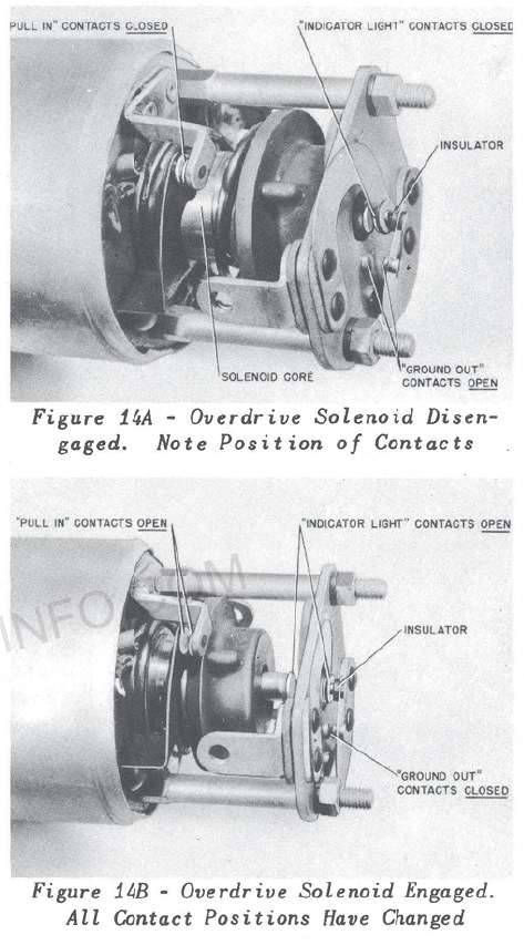
Posted on: 2009/8/27 20:39
|
|||
|
||||
|
Re: Continuing on the Overdrive
|
||||
|---|---|---|---|---|
|
Home away from home
|
This is looking pretty good!
I disconnected, cleaned and reconnected all the leads at the relay, and by-passed the #3 wire last night and got what seemed to be a perfect result. Grounding at the governor or at terminal 5 actuates the solenoid and keeps it actuated. I replaced a portion of the #3 wire at the solenoid end where there was clearly a lot of wear and maybe 50% of the strands looked broken. Same result now, and with the solenoid actuated, I can move the relay, the wires around the relay, the harness and the wires at the solenid end and the solenoid stays out until I disconnect the ground. Now, I just feel it can't be that easy, but I am hopeful. I am awaiting new solenoid gaskets to close it up and test drive. I get a reading of about 6.2 on my volt meter at terminal #1. When I do the test after fixing the wire, I get about 6.2 at terminal 4, but only about 4.6 at terminal 3. Does this indicate a potential problem? Also, in removing the relay to clean the wires and inspect the mounting tabs, I still noted that the ground-out points were still closed (with the relay out of the car). Once I pop them opened, of course, they stay open. Is there a reason that they would normally be closed and should they remain closed after the power is off (which I noticed before) and even after the relay is disconnected? HH - you are correct, I do have the short wire loom with the black connectors. It goes from the solenoid, over the trans to the other side and hooks into the harness going to the relay. All the connectors seemed to be good. If I experience issues when I test drive, I will probably replace this harness as the solenoid wires are showing some wear, and it doesn't look too tough to replace. Thanks for all the help. This forum is really a great resource. I probably wouldn't try a lot of this on my own, but with knowledgable people to help, it removes a lot of the concern of getting in over your head. Thanks to all who have helped out. I'll let you know the results of the road test early next week!
Posted on: 2009/8/28 10:31
|
|||
|
1941 Touring Sedan
1952 250 Convertible 1932 902 Rumble seat Coupe Who is John Galt?
|
||||
|
||||


