|
Re: Pusbutton schematics.
|
||||
|---|---|---|---|---|
|
Forum Ambassador

|
Randy -
I did expect there would be some legitimate cases when the vehicle needed to be moved with ignition off (e.g. - pushing, towing, etc.). Although there automatic car washes of that type are still in use, I don't use 'em - at least not with the Packards. Yet, you've given me pause for further thought. Splicing the yellow and tan wires, per STB 56T-25, merely replaces the connection that was previously made when the park relay was energized - effectively restoring the circuit as it was intended prior to actual production (per SC Vol. 29, No. 11). Splicing the white, red/white, and orange wires, per same STB, merely replaces the point at which all three wires met - at a common terminal on the relay. However, why do they add a 9A fuse for the white wire (which feeds power to the control panel buss bars), when none was required previously? BTW, in comparing diagrams among the various articles/bulletins, it appears that WHITE wire was once YELLOW on some cars - perhaps only the early production cars that were built with the control (battery) relay (which was to be eliminated in the field, per SC Vol. 30, No. 1. For those cases when I need to bypass the auto-park relay function, I'm thinking of installing a remote DPDT switch wired in such fashion so as to open the circuit provided by the green feed wire from the breaker to the park relay, yet complete the circuit between the tan and yellow wires. That may seem like an additional layer of complication, but it's really not much more than the factory provision of a cut-off switch, or even the manual control kit, for the Torsion-Level system.
Posted on: 2011/9/10 10:18
|
|||
|
||||
|
Re: Pusbutton schematics.
|
||||
|---|---|---|---|---|
|
Forum Ambassador
|
Howard -
Thanks for the clarification. Yes, since a yellow wire for the pushbutton "P" circuit was added in conjunction with the park relay, I see how that might be confused with the original yellow feed wire for the control panel. Perhaps yellow was chosen, originally, for that feed wire since - as you noted - it got its power from the ballast resistor. I had wondered about using a relay, but backed away from that, thinking we don't need the additional current draw. I'm no engineer, but not sure that we're dealing with enough amperage to merit a relay over a good switch. Thinking further on this, perhaps I don't need to complete the circuit between yellow and tan wires at all, since bypass would only be needed with ignition OFF - at which point, power feed to pushbutton control panel is cut-off, anyway. So, a simple, remotely-mounted, SPST switch and a pair of new green wires, installed in place of the original green wire between the breaker and the park relay might be all that is needed to temporarily deactivate the park relay. Again, not much different than the cut-off switch for the automatic levelling system. Yet, thanks to your insight, I also plan to install a 9A fuse/holder between the white wire and the corresponding terminal on the park relay.
Posted on: 2011/9/10 11:05
|
|||
|
||||
|
Re: Pusbutton schematics.
|
||||
|---|---|---|---|---|
|
Forum Ambassador

|
Since this discussion came up, decided to make a manual select autopark. Brian & Randy mentioned a toggle switch and I agree that was the simplest way to go.
I wanted my setup to be almost non detectable and happened to have a burned out relay to play with. Gutted that relay can and installed everything inside. If anyone wanted to do the bypass without having the bad or extra relay or not doing anything to car 2 minutes with a screwdriver wouldn't reverse, it can be done by using an ordinary toggle switch externally. Connect as shown on the schematic and hide the switch somewhere. Moving toggle one direction, all works as designed. Moving the other direction, 12v is disconnected from relay contact which would normally place trans in park when ign is turned off. The relay still operates with ignition but without the 12v on the one terminal, can do nothing when turned off. An option if the switch and a new relay is installed in the relay can is use a different switch (3 pole DT instead of DPDT) and that third set of contacts to keep the relay from operating--or mount an external 3P switch & terminal strip on a bracket near the relay and relocate the power wires. The current second set of switch contacts connects the PB directly to sector for complete manual control. Not really necessary unless the relay fails or is turned off. I threw it in as a failsafe since this dead relay had burned out the coil and it would have been nice to have that feature at the time. Attach file:  (93.97 KB) (93.97 KB) (156.06 KB) (156.06 KB)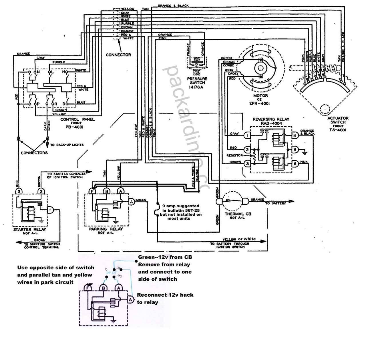
Posted on: 2011/11/1 18:22
|
|||
|
Howard
|
||||
|
||||


