|
Re: Super 8 Starter Wiring need some help!
|
||||
|---|---|---|---|---|
|
Forum Ambassador
|
That appears to be the Autolite starter and solenoid which was used on the 356 engine thru 50.. The solenoid is actually operated by a small relay inside the square housing. The coil of that relay is what is brought out on the two small screw terminals.
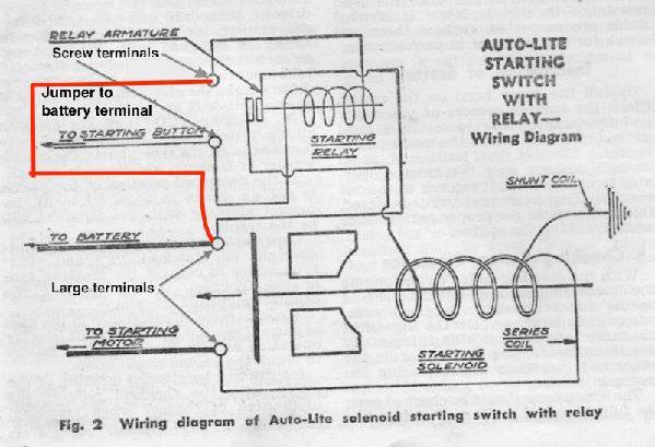
There are two ways the start circuit was done prewar. The first is the starter needs a ground from the starter switch. Unless the car has had a modification, this method is shown on diagrams for the models with the starter button. On those that need a ground, usually the starter will energize by pushing the button even with the ign off. On models with the accelerator pedal start switch the starter needs a voltage and stater does not operate when ign is off. Some of the original ground needing models had a modification to make the circuit work like the accelerator switch type. There is a safety circuit built in so in both cases the ground is provided either via the generator or in some models an extra set of contacts in the voltage regulator. This safety circuit prevents the starter from operating after the engine is running. On models with a ground requirement, there is a very small almost hidden metal strip which jumpers between the battery post and one of the small screw terminals on the solenoid. If the solenoid has been painted the jumper may be painted over too. The other small solenoid terminal goes to the starter switch and after going thru the switch winds up at the voltage regulator. On regulators with an extra terminal labeled S or start there is a separate set of contacts associated with the cutout relay which connect to ground. Pushing the start button completes the ground to the solenoid. The safety circuit works as follows: For the extra terminal on the regulator type, once the generator is putting out voltage and the cutout relay closes the extra contacts are opened so the starter button has no ground and cannot operate the solenoid. On regular voltage regulators with 3 terminals, the wire is connected to the ARM terminal which then goes thru the generator and finds a ground thru the brushes and armature windings. On those cars, when the generator starts putting out a voltage, that voltage is fed back to the regulator and one side of the starter switch. Since there is also voltage on the other side of the switch direct from the battery via the small jumper feeding the relay in the solenoid, the voltages are almost equal so there is not enough difference across the relay coil to bring in the relay and energize the solenoid. On models with the accelerator switch, there is no small jumper at the solenoid so the voltage is taken from the ign switch. It goes thru the carb switch to one of the screw terminals on the solenoid The other start terminal is connected to the regulator ARM terminal and just as before, has ground coming from the generator. Here is the Autolite solenoid diagram showing the jumper setup. The AEA diagrams available on the PAC site show the wiring. Depending on the quality of the print, the jumper is indicated by a very short and almost hidden line between the battery connection terminal and one of the small start terminals.
Posted on: 2018/7/13 18:24
|
|||
|
Howard
|
||||
|
||||
|
Re: Super 8 Starter Wiring need some help!
|
||||
|---|---|---|---|---|
|
Home away from home
|
it most likely is because of the test stand and how it's configured, probably for a negative ground motor.
The wiring diagram is for in the car. The motor would be positively(+) grounded when in the car. So in order for the starter current to flow, it's needs to have that same connection. Need to think in reverse current flow from what your used to. Positive(+) to ground, negative(-) to battery.
Posted on: 2018/7/13 19:28
|
|||
|
||||
|
Re: Super 8 Starter Wiring need some help!
|
||||
|---|---|---|---|---|
|
Forum Ambassador
|
Unlike modern permanent magnet starters and motors, field coil type starters as well as relays and solenoids of that era are not polarity sensitive as evidenced by the many Packard and other cars with positive ground systems that have been purposely changed or accidentally wound up with a reversed battery.
Posted on: 2018/7/13 19:52
|
|||
|
Howard
|
||||
|
||||
|
Re: Super 8 Starter Wiring need some help!
|
||||
|---|---|---|---|---|
|
Home away from home
|
There are a couple things that bother me about this..........
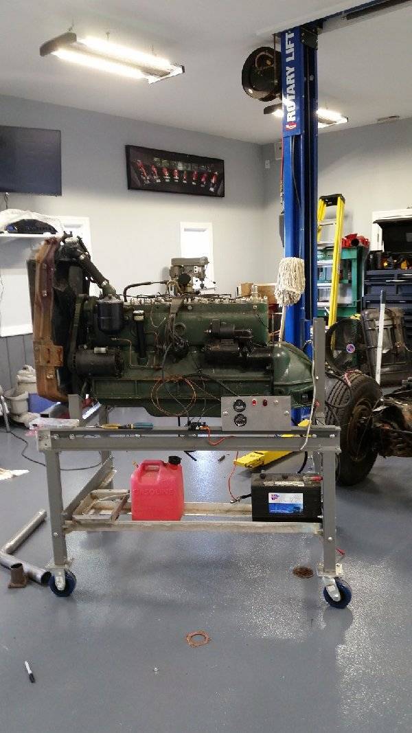
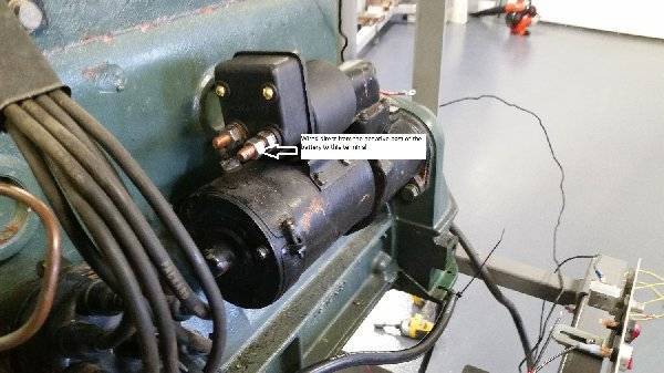
How is the post on the starter motor tied into the solenoid? The 6 cylinder uses a copper "L" shaped strip tied from the solenoid to the starter post. This doesn't appear to set up in a similar fashion. What is the connection between the starter and the solenoid? Secondly. when I ran a cable from the " - " of the battery directly to the terminal of the starter relay, the entire unit started to generate heat. According to the wiring diagram, it should be a direct connection from the battery to the starter. What I'm looking for is how do I get power from the battery to the starter and from a Push Button to solenoid? At wit's end..........
Posted on: 2018/7/13 20:50
|
|||
|
Steve P
Forest, Va 1929 645 Dual Cowl Phaeton 1937 120C Conv Coupe 1940 1389 Conv Coupe 1940 1377 Super 8 160 Conv Sedan |
||||
|
||||
|
Re: Super 8 Starter Wiring need some help!
|
||||
|---|---|---|---|---|
|
Forum Ambassador
|
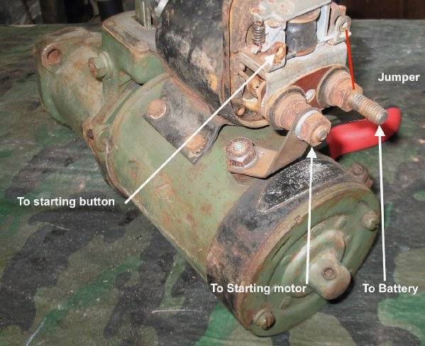
Here is a photo of a typical setup as it would be from the factory using the grounded starter switch. The labels are the same as was used in the drawing posted earlier. I don't have a factory voltage supply jumper on this starter but it is usually a thin copper strip. That could have been changed over the years to a wire or ??
IF the circuit has been modified so as to use the later circuit with voltage coming from the button instead of a ground the ground for the relay could be provided one of two ways. Keeping the safety circuit intact would be preferred but there were issues with the circuit in some cars -- particularly if the generator might have had some issues of its own. In that case the ground could be provided directly. Factory bulletins had the mechanics remove the wire coming from the starter button at the regulator ARM terminal and ground it directly. It is also possible the factory jumper that was used to provide voltage in the grounded switch circuit was removed or repurposed and connected to some ground point on the starter or solenoid instead. Mechanics could have done it any number of ways so look or feel very carefully for any kind of connection between either of the small screw terminals to anywhere else on the solenoid or motor.. The solenoid has two windings. The shunt winding in the drawing is a very thin wire connecting to ground and is used only for holding the solenoid in once it has been energized. It cannot pull the solenoid in by itself. The one labeled series winding is very heavy wire that is for doing the heavy work but can only be for short time use. It goes thru the starter motor windings to find a ground much as the solenoid relay safety circuit goes thru the generator for its ground. The starter motor must be connected to the solenoid for it to work. Once the series winding has done the heavy job of pulling in the plunger it is effectively shorted out by the plunger connecting the motor terminal directly to the battery so quits doing any work leaving the shunt winding only to hold the plunger in. The battery cable connects to the long terminal post which should be the one on the right in the photo. When the solenoid energizes a contact inside connects the battery terminal to the short post which has a buss bar direct to the motor. Assuming you are working on the 40 model in your signature, you can download the AEA diagram for you car from the PAC site it you do not have one. It very clearly shows the factory wiring from the solenoid thru the starter button to the regulator for the original circuit. If you car has been modified to more follow the 42 circuit which needs voltage instead of ground then it is anyone's guess exactly how it was done. As far as I know Packard never published a recommended method for that modification yet there are several cars I have seen which have been changed so the ign switch has to be on for the starter to work..
Posted on: 2018/7/13 22:24
|
|||
|
Howard
|
||||
|
||||
|
Re: Super 8 Starter Wiring need some help!
|
||||
|---|---|---|---|---|
|
Home away from home

|
Hi, Steve,
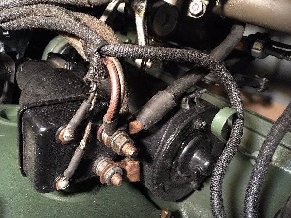
This is the starter set-up on the Duchess, my '40 1377, if it helps. I moved the overdrive wire to the distributor out of the way for the picture. Double click it to get the picture oriented correctly. Joe
Posted on: 2018/7/14 9:17
|
|||
|
||||
|
Re: Super 8 Starter Wiring need some help!
|
||||
|---|---|---|---|---|
|
Forum Ambassador
|
Joe, does your starter work any time the button is pushed or does it have the later circuit that only works with the ign key on? Is your voltage regulator the original version with the extra terminal on the opposite side of the case from the other 3? Am curious because the way the solenoid is wired doesn't appear to match the 40 and 41 Su8 AEA diagrams but does look like the 42. Am wondering if yours was modified or if Packard did something different than the AEA diagrams show. I don't have a good enough print of the official 40 Packard diagram to read the tiny wire number labels and trace the wires.
Posted on: 2018/7/14 9:28
|
|||
|
Howard
|
||||
|
||||
|
Re: Super 8 Starter Wiring need some help!
|
||||
|---|---|---|---|---|
|
Home away from home

|
My starter button works the starter without the key on.
I know you mentioned this once before. This may be the '48 version. I have 2 starters for the 356. One we'll put on the '40 version. However it's wired, it works fine. I have to leave but will check back later.
Posted on: 2018/7/14 9:42
|
|||
|
||||
|
Re: Super 8 Starter Wiring need some help!
|
||||
|---|---|---|---|---|
|
Home away from home
|
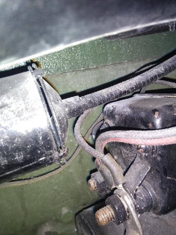
Here is my 1940 Super, should be all original. Could not get everything. With key off starter will turn with button, but will not start.
Posted on: 2018/7/14 10:33
|
|||
|
||||

 (137.24 KB)