|
Re: Coil wiring diagram /1954 pacific/cruising rpm engine bogging/coils
|
||||
|---|---|---|---|---|
|
Home away from home
|
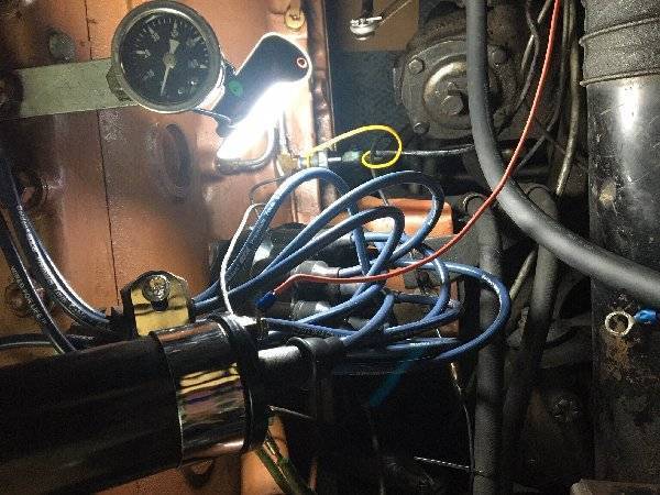
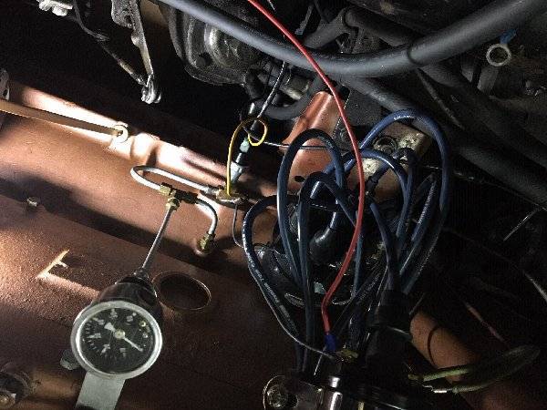
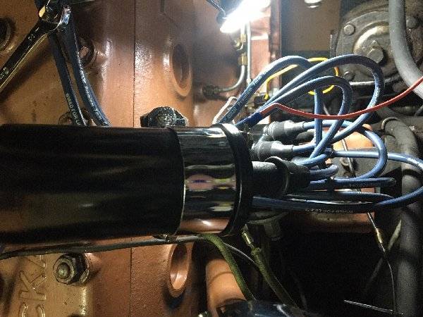
Aloha Howard. So this is what we have. The end is near. 1954 Packard Pacific with 359 L8 and GM 700R4 trans. The car cranked but wouldn't start. Car has auxiliary electric fuel pump. Turns out the engine was flooded. Screw driver, ether and pedal to floor. Problem solved. But, in process I changed coil, plugs and rotor. And mistakenly reversed the coil polarity. Stock 1954 wiring for coil has 2 wires. Ignition wire to Neg. terminal and Distributor wire to Pos. terminal. My car when arrived had a ground wire to the coil bracket from Pos. terminal and both the ignition wire and distributor wire attached to the Neg. terminal.
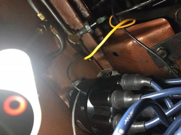
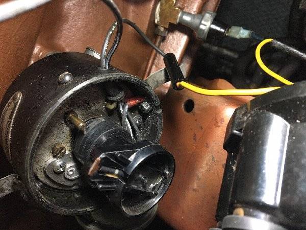
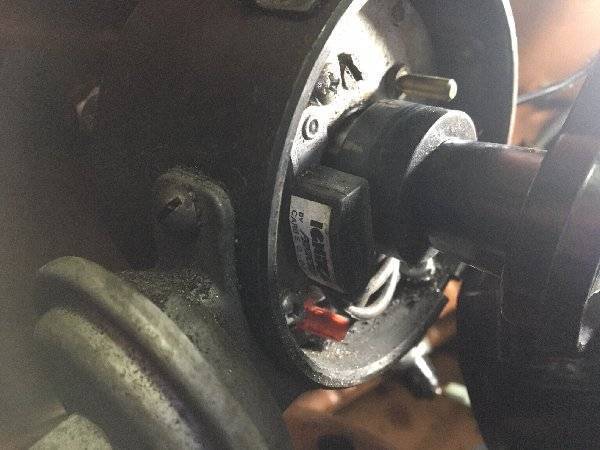
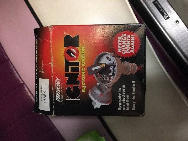
Net :"A coil with reversed polarity will have about a twenty percent lower output which may not show up at idle and low rpms, but can cause an engine to miss or stumble under load and at higher engine cruising rpms." Once the polarity was sorted out I bogarted multiple after-market coils all with different primary and secondary resistances. Turns our the original one was ok as well. I added a new Pertronix Flamethrower #40011 coil and ordered a Brillman Stinger (OCD). Turns out the distributor has another orange wire coming out of it!! The car has a tachometer but it also has a Pertronix 1188K ignitor!! I wasn't sure until I took the cap off and got in there. Hence your suggestions were correct and due to the ignitor will keep the wires where they are. Again, the bogging seems to be gone. Not sure what would happen if I put the distributor wire back onto the Pos. terminal though.From picture, my rotor isn't in No.1 spot, thoughts? Thanks again.
Posted on: 2019/11/19 20:33
|
|||
|
||||
|
Re: Coil wiring question
|
||||
|---|---|---|---|---|
|
Home away from home
|
Just a few more points on this 6 volt positive ground Pertronix stuff:
If the subject car is equipped with an overdrive (not the case in this thread) there will likely be two wires attached to the positive coil binding post. One wire goes to the ignition point set, while the other goes to the overdrive kick-down switch. When I contacted Pertronix about how the kick-down functionality could be retained they provided the attached schematic . . . essentially a 7 ohm, 5 watt resistor in series with the kick-down circuit. If the car is currently AutoLite equipped, and a Pertronix coil is used, then the installer must provide a coil hold-down strap. Seems the Delco equipped cars used a 'bare' coil, just like the Pertronix replacement items, while the AutoLite coil had an integral coil clamp. See group 4.12033 in the parts book, and note the strap is only used on Delco equipped vehicles. Not a big deal to make one out of sheet stock, just be aware that 'some assembly is required' on AutoLite equipped cars. dp
Posted on: 2019/11/19 21:01
|
|||
|
||||
|
Re: Coil wiring question
|
||||
|---|---|---|---|---|
|
Forum Ambassador
|
As long as it starts and run with the wiring as is I would not change anything if the coil polarity is correct. If not then swapping the wires to the proper terminals for a positive ground should not cause any problems as long as both are swapped over and if more than one wire on the same terminal, those stay together.
The distributor looks to have been installed a tooth or two off causing the rotor to be in a different spot than Packard suggests. Not a big deal as long as you are aware of it although it might be good to make sure the "new" #1 terminal is marked or noted in case someone else works on the car and tries to use original instructions or diagrams.
Posted on: 2019/11/19 21:30
|
|||
|
Howard
|
||||
|
||||
|
Re: Coil wiring question
|
||||
|---|---|---|---|---|
|
Home away from home
|
Great, thank you very much David.
Posted on: 2019/11/20 7:54
|
|||
|
||||
|
Re: Coil wiring question
|
||||
|---|---|---|---|---|
|
Home away from home
|
Cool, thanks Howard!
Posted on: 2019/11/20 7:58
|
|||
|
||||

 (307.42 KB)