|
Re: electric shift
|
||||
|---|---|---|---|---|
|
Forum Ambassador

|
I don't know which drawing you might be using but here is a complete diagram showing all contacts and the internal motor connections.
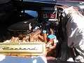
 The pink and orange/black end wires of the finger section do not get power directly but rather connect power to relay coils to drive the motor one way or the other. The direction driven is depending on which one of the other fingers is providing the power via one of the push buttons being selected and is touching which ever side of the split segment is connecting to an end finger. Once the segment drives and the center dead spot lands at the powered finger from PB, the connection is broken and everything stops. Note also there were two different PB looms. Early looms had power to the buttons and fingers coming from the ballast resistor via a yellow wire connecting to the auto park relay which was used a a tie point to supply power to the pressure switch and PBs. Because of wires that were spliced inside the loom, there was only one of the other wires also connecting to the yellow wire at the auto park relay. Since there was also a yellow wire coming from the button assy for the park button, to avoid confusion later looms changed the yellow wire coming from ballast resistor to a white wire. They also eliminated the internal splice and brought both the red/white and orange wires to the auto park relay for the tie point connection.. If your wire colors at the finger assy looks like this then it is OK Note the pink wire end finger that is completely off the sector. This was a frequent problem if the actuator over travelled and quite often the actuator had to be removed to place the finger back on the sector. Some luck was had by chamfering or rounding the sector end slightly for a kind of ramp effect and with those, Ross has had some success manually driving the actuator to get the finger back in contact. More often though, if either end finger has fallen completely off and is going to be hit by the actuator at either end as this one would be, then I believe the only solution is to remove and repair. Trying to drive the actuator with a finger in the way will most likely only damage the finger or the support. 
Posted on: Yesterday 12:22
|
|||
|
Howard
|
||||
|
||||
|
Re: electric shift
|
||||
|---|---|---|---|---|
|
Quite a regular

|
Hi Howard:
Wiring in my actuator looks exactly like the picture you posted. I'm using the Packard shop manual with the 56 supplement on the electric shifter, and referring to page 116, figure 237 where they describe testing the wiring. They have you turn the worm gear until the open spot between the contact strips lines up with the centre screw on the finger assy. The test just doesn't work as described. My problem is that I can't seem to get the actuator properly set on the trans shaft so that it will go into all gears. I can set it in reverse no problem, but then am stuck in low gear on the drive and high buttons. Moving the actuator up slightly [toward the top of the trans], it will still be in reverse on the reverse button, but will be in low gear on the drive button, and if I then push the high button it will shift into high. If I push the high button when first coming out of reverse, the car starts out in low and will shift to high, which would seem to indicate it is actually in drive as opposed to high. At this point it will not go into neutral, and wants to back up in low. Moving the actuator upward a bit more, and I lose reverse and the car wants to go forward. I've been struggling with this since last fall when I put a new seal on the shifter arm, and you know what a pain it is to remove the actuator from the transmission.
Posted on: Yesterday 12:53
|
|||
|
||||
|
Re: electric shift
|
||||
|---|---|---|---|---|
|
Home away from home

|
Does the shaft itself have rotary play? If you have more than something like 1/32nd of an inch measured 1 in away from the center of the shaft then it is too loose on the inside linkage and you need to tighten up the set screw and jam nut again. There is also a roll pin that you can install which really helps the situation.
Posted on: Yesterday 13:17
|
|||
|
1955 400 | Registry | Project Blog
1955 Clipper Deluxe | Registry | Project Blog 1955 Clipper Super Panama | Registry Email (Parts/service inquiries only, please. Post all questions on the forum.) service@ultramatic.info |
||||
|
||||
|
Re: electric shift
|
||||
|---|---|---|---|---|
|
Home away from home
|
You need to make sure the bolt is set right.
When tightening it move to motor up an down to feel the recess That set right.. then you need to play around with motor In P Move it up down a little then try the buttons keep trying till you get it.
Posted on: Yesterday 13:34
|
|||
|
Riki
|
||||
|
||||
|
Re: electric shift
|
||||
|---|---|---|---|---|
|
Forum Ambassador
|
Quote:
You may have a wallowed out set screw on the shift arm inside the transmission. That part sits on the gear selection shaft and is the linkage between that shaft and the valve body plunger that routes fluid flow to operate the trans in the selected gear range. The arm is made of pot metal and can get wallowed out or stripped on its set screw. The Pushbutton actuator just rotates the shaft into one of six positions. The rest is up to the transmission.
Posted on: Today 11:23
|
|||
|
||||
|
Re: electric shift
|
||||
|---|---|---|---|---|
|
Forum Ambassador
|
In addition to the issues mentioned that are caused by the possibly loose setscrew and locknut, there is also a mechanical stop piece installed to prevent overtravel when going into reverse. The setscrew also holds the stop in position. Because of a difference between the cast iron 55 case and the 56 aluminum case, as I recall the stop is positioned differently in 56 than is shown in the 55 photos which were used in the service manual. Make sure the stop is tight and positioned correctly so you can get full valve travel into reverse position by the shaft and lever..
If you do find the lever and setscrew is loose, adjust things back to normal and in addition to tightening the setscrew and locknut, drill the lever and shaft so you can add a 1/8" roll pin to keep the two in alignment.
Posted on: Today 11:53
|
|||
|
Howard
|
||||
|
||||


