|
Re: 1940 Super 8 160 Model 1803 Project
|
||||
|---|---|---|---|---|
|
Forum Ambassador

|
After taking a night off to do some research on the valve gauge block situation I got back at it after dinner out with friends this evening. Firstly, I find according to the 1940 Super 8 owners manual / service manual supplement you need only the tappet installed with no oil in it what so ever and to depress the plunger all the way down; measuring with feeler gauge no less than .030" and no more than .070" clearance. I was very surprised to learn this given all the discussion about the gauge block method. I am also surprised to find that Packard engineers wanted the lifter plunger sunk that deep into the lifter body, but that is what they wanted and they built a fine silent running engine that provided great long-term service.
One of our forum members was kind enough to provide gauge block specs today. I compared the gauge block specs to fully compressed lifter and what do you know... they are exactly the same! So, after all the discussion about the gauge block, and understanding that this tool would make it very quick and efficient in checking valve stem to tappet clearance, I felt compelled to go ahead and make one to use this evening. Grabbed some steel and got after it. Not a tough or terribly time consuming project. Below are a few images of DIY gauge block production. Attach file:  (41.07 KB) (41.07 KB)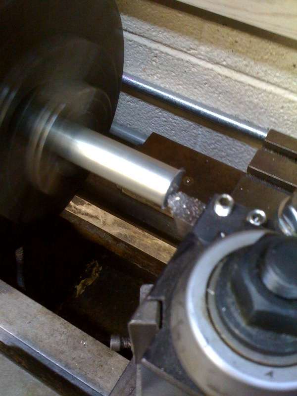 (44.74 KB) (44.74 KB)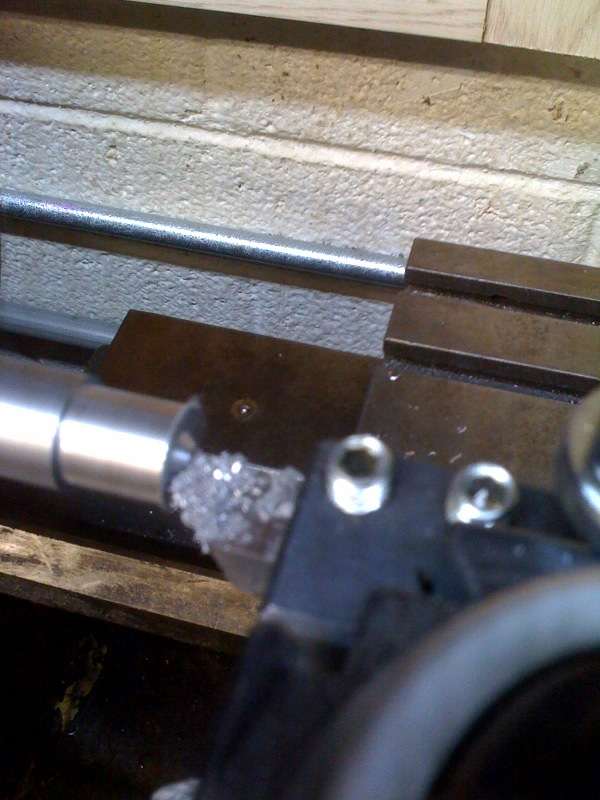 (41.74 KB) (41.74 KB)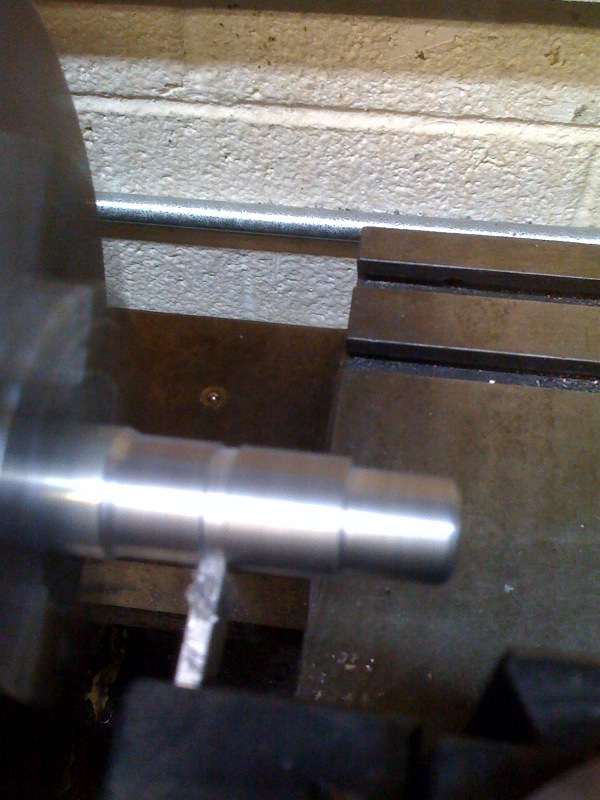 (41.74 KB) (41.74 KB)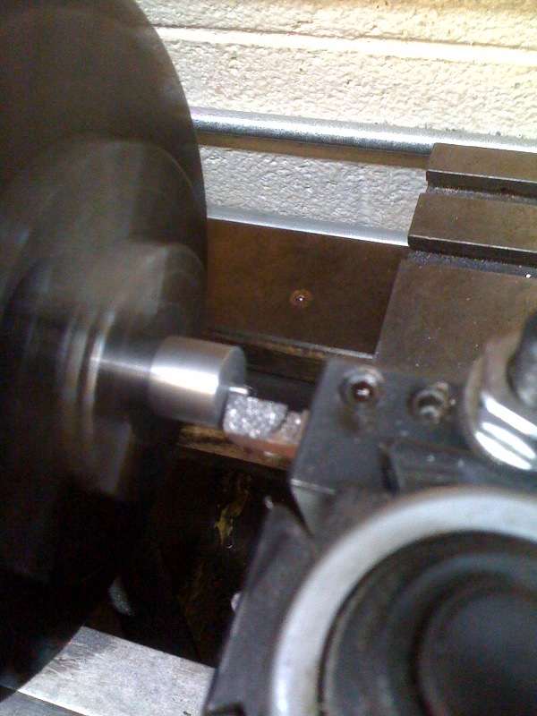 (38.17 KB) (38.17 KB)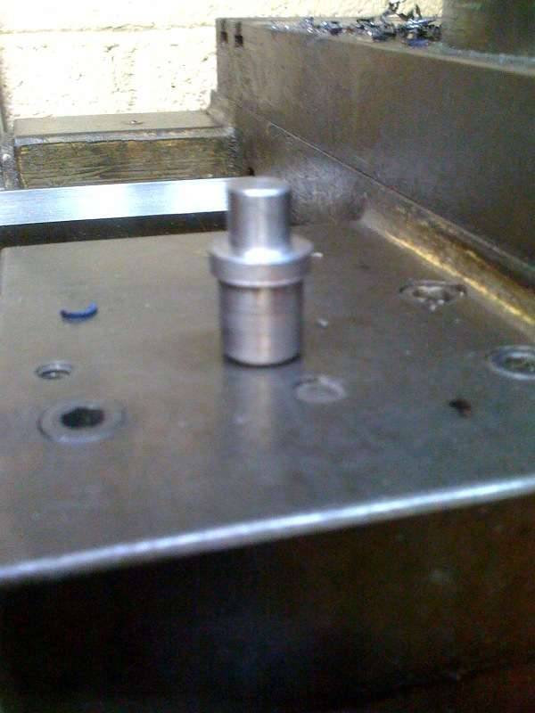
Posted on: 2011/5/14 2:33
|
|||
|
||||
|
Re: 1940 Super 8 160 Model 1803 Project
|
||||
|---|---|---|---|---|
|
Forum Ambassador
|
Armed with gauge block in hand and feeler gauge in the other, I performed the checks. As luck would have it the .030" easily went in and the .070" would not. How nice to know the valve to lifter clearance is perfect and to also be reassured the damage was not caused by improper clearances or improper assembly.
I also repeated the check simply using the empty replacement lifter and said feeler gauges fully depressing the lifter plunger and checking go/no go and got perfectly identical measurements and results. So, we have learned that while the gauge block is neat to have, it seems the plunger depth can be set with the emptied and compressed lifter assembly installed. A very interesting and enlightening exercise. Attach file: (30.12 KB)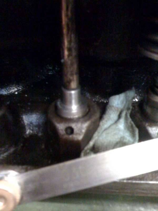 (29.62 KB) (29.62 KB)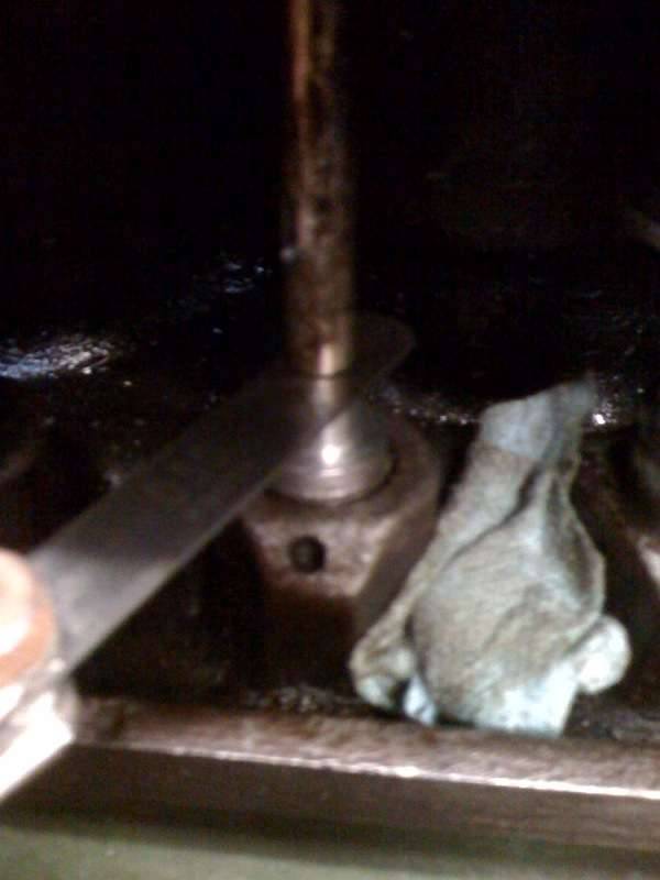
Posted on: 2011/5/14 2:37
|
|||
|
||||
|
Re: 1940 Super 8 160 Model 1803 Project
|
||||
|---|---|---|---|---|
|
Home away from home

|
Cool to see that process, Jim. Wow. I want to see your garage. A garage with REAL equipment.
But in the DIY department, the clueless innovate. When I was going through my lifters, that little oil hole has to be absolutely clean for the plunger to go down. I bought my plug gauge from the Pacific NW Region of PI. Here are the instructions they sent. "Place the gauge in the lifter body and while holding the valve down on its seat, check the clearance between the valve stem and the gauge using a feeler gauge. The clearance should be more than .030 inch and less than .070 inch. Repeat for each valve. Be sure to see that each piston is at the top of its compression stroke when checking the corresponding valves for clearance. When installing the hydraulic lift into the tappet, it is advisable to have removed all of the oil from inside the hydraulic unit. Otherwise, the valve may be held open until the excess oil escapes from the lifter. With good tight lifters this could take some time. The lifters will pump back up over a period of time. This can take as much as 20 to 30 minutes to become totally quiet depending on oil pressure." I realize you said most of that. I think I read in one of the service manuals that it can take an hour for the lifters to pump up. As a clueless DIYer who was terrified of mismatching plungers after reading all the warnings (i.e. If mismatched, return to factory.), I used a little berry box with a masonite bottom. Turned it upside down and drilled 1/2" holes in it to hold the lifters while I cleaned them one at a time. (It's spent some time in the paint room since, holding smaller items for painting.)The lifters fit in the hole like the gauge does in the small picture. And to make sure I didn't lose any keepers, I used a couple of sizes of rubber plugs to fill the holes in the block. I know, stone age, but for me, it worked. Joe Attach file: (86.58 KB)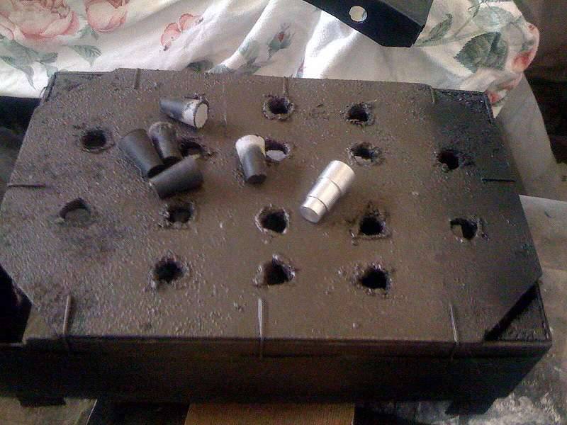 (34.06 KB) (34.06 KB)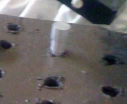
Posted on: 2011/5/14 10:19
|
|||
|
||||
|
Re: 1940 Super 8 160 Model 1803 Project
|
||||
|---|---|---|---|---|
|
Forum Ambassador

|
Congrats! Good preparation and thinking, you've done your homework and what most of us who have done dozens of these valve jobs routinely do. I have a rack to retain the valves in the order they were in the engine, and ditto for the lifters. As to remembering to put corks or similar into the oil return holes, a lot of folks have learned that the hard way.
Yes, using the gauge block is much simplier, whether it's more or less accurate I don't know but the fact that Packard dropped the recommendation of the alternative method probably has some basis. Some one earlier, perhaps in this thread, made a comment about Packard's designing these lifters or something like that - Packard didn't design them, they were designed, patented and manufactured by Wilcox-Rich and are of the same design though slightly different than the Wilcox-Rich units used in the flathead Cadillac V8 (345 ci). Pierce Arrow had hydraulic lifters in the in-line 8s well before most anyone else - don't know who made these units but if anyone knows, I'd like to hear.
Posted on: 2011/5/14 13:28
|
|||
|
||||
|
Re: 1940 Super 8 160 Model 1803 Project
|
||||
|---|---|---|---|---|
|
Forum Ambassador
|
Quote:
Dave, I was just reading back a bit and realized I never replied to these questions. I apologize! No, I did not do a compression check. I did a plug drop check and found nice even idle drop from cylinder to cylinder, with just the slightest difference in cylinder 6. The car ran so well, did not smoke a bit (after steps taken described earlier in this thread), and made almost no blow by I had little need to do one. Oddly, I never even had the occasion to pull a spark plug till the other evening. On the front engine mount question, a fellow in Southern California casts them. I can PM you his contact info if you like. I am very pleased with the fit and finish.
Posted on: 2011/5/14 23:15
|
|||
|
||||
|
Re: 1940 Super 8 160 Model 1803 Project
|
||||
|---|---|---|---|---|
|
Forum Ambassador
|
Quote:
Joe, all excellent information! You were well served to take all these precautions because I know of folks that obtained the services of "professionals" who did not take these precautions and delivered a Klackard as the finished product. Myself and others are well served by these reminders!
Posted on: 2011/5/14 23:28
|
|||
|
||||
|
Re: 1940 Super 8 160 Model 1803 Project
|
||||
|---|---|---|---|---|
|
Forum Ambassador
|
Quote:
Dave if you meant my post stating "I am also surprised to find that Packard engineers wanted the lifter plunger sunk that deep into the lifter body, but that is what they wanted and they built a fine silent running engine that provided great long-term service." I really wasn't directly commenting on who designed the part as much as the directive on plunger depth in the lifter body. With that said, I am delighted to learn a little about these early lifters and never new Pierce Arrow had hydraulic lifters in the in-line 8s well before most anyone else. I was always under the false impression that Packard was one of the earliest. These little tidbits folks share here are a big part of making the threads so interesting! Thanks...
Posted on: 2011/5/14 23:35
|
|||
|
||||
|
Re: 1940 Super 8 160 Model 1803 Project
|
||||
|---|---|---|---|---|
|
Home away from home

|
Nearly identical Wilcox-Rich lifters were used in Lincoln V12 38-48, V8 49-51, Cadillac V8 38-48, Packard 356 40-50, some 288,327 and all 359 48-54. We make them all.
The precision fit that cannot be mixed is the hydraulic tappet body to the hydraulic tappet piston, they are fitted to the tenths of thousands. The cam follower to hydraulic tappet is not a precision fit, they can be mixed between valves. The cam followers shoiuld be placed back to the position they came from, they have a wear pattern which mates to that of the individual cam lobe that should not be disturbed.
Posted on: 2011/5/15 3:02
|
|||
|
||||
|
Re: 1940 Super 8 160 Model 1803 Project
|
||||
|---|---|---|---|---|
|
Forum Ambassador
|
Two full days of stripping and prepping sundry parts. Spent Saturday stripping the starter assembly. For the life of me, I can't imagine why the rebuild (or who ever) would have painted it yellow, followed by the Detroit Diesel green, with a final topcoat of Packard engine enamel to hide the prior offenses. Why not just paint it black? Oh well...
Today was stripping and prepping road draft tube, oil fill, oil filter canister, and all the copper lines that connect distributor to carb, oil filter, manifold drain, and spark plug wire holder. It never ceases to amaze me how long it takes to do this kind of work. While I am not restoring the car at this time, I do feel any work done should be performed in the spirit of putting back to as delivered standards. Though much of this work really will not make a big difference in the way the car performs, it is amounts to pride in workmanship. Prepping these sundry parts and pieces reminds me of just how much Mal, Kev, West, and Joe have all gone through. While this kind of work is not new to me, I have enjoyed following their project threads and inspired by each of their respective detail, workmanship, and final outcome. On to prepping the cylinder head, manifold assembly, and sourcing odds and ends. Speaking of odds and ends, I bought a lower radiator connection pipe made of stainless steel today. That should last forever! Also, by chance... would anyone reading this thread have a spare proper clamp for the 1.5 inch road draft tube to valve cover attachment? Mine seems to have changed to a gates style hose clamp at some point. Attach file: (51.85 KB)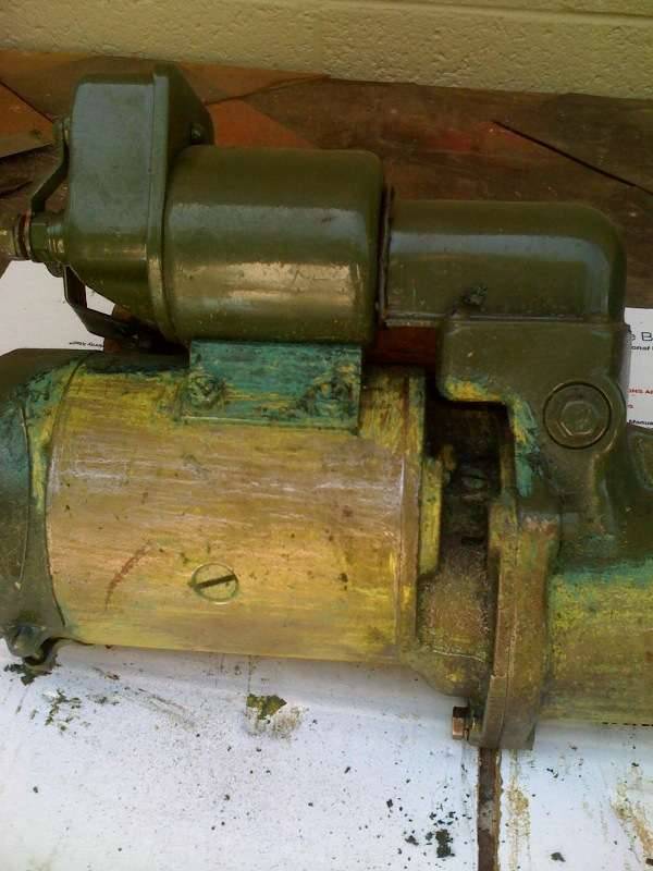 (51.12 KB) (51.12 KB)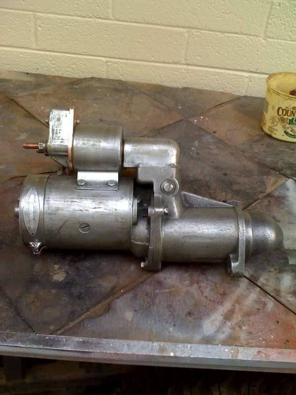 (57.88 KB) (57.88 KB)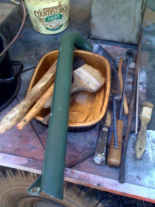 (61.12 KB) (61.12 KB) (71.43 KB) (71.43 KB)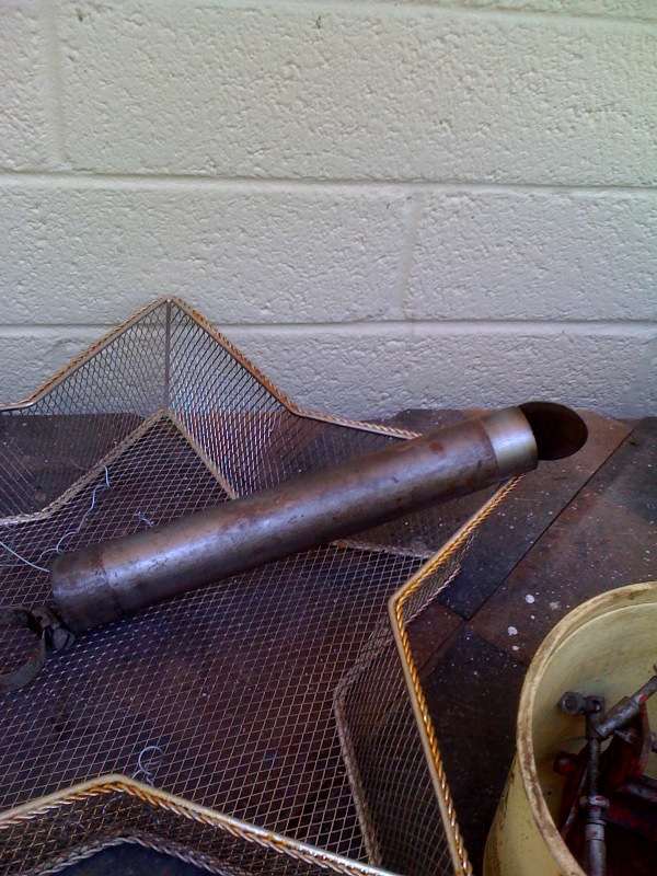 (36.56 KB) (36.56 KB) (43.50 KB) (43.50 KB) (46.30 KB) (46.30 KB)
Posted on: 2011/5/15 23:39
|
|||
|
||||


