|
Re: A Tale of Two Patricians
|
||||
|---|---|---|---|---|
|
Home away from home

|
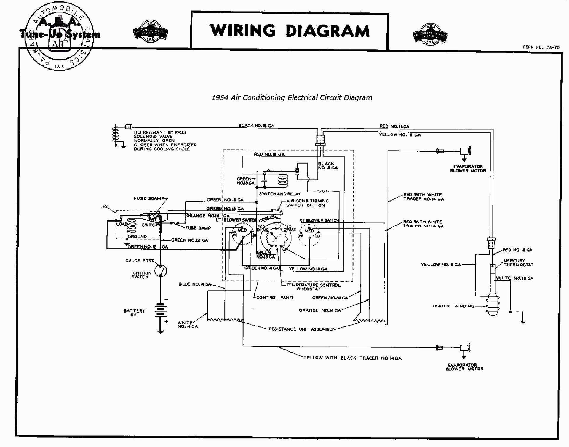
Howard, thank you! That's a different diagram than I have but is very similar. What I am looking for, though, is the layout of each component as it us in the car and how the wires go to each one.
Posted on: 2021/2/13 3:57
|
|||
|
||||
|
Re: A Tale of Two Patricians
|
||||
|---|---|---|---|---|
|
Forum Ambassador

|
Unless you can come up with a factory blueprint of the entire system I doubt you are going to find any published information at that detail level in anything Packard released to dealers or the aftermarket people. You can get a good idea of original component layout from the photos in the SM and a few in various SC articles but if you are going to try and adapt modern components to an original or repro box then the factory layout would need to be eliminated or considerably modified so might not be that useful anyway.
If you have or are going to search for an original system to install then the factory layout info in the SM would be helpful in putting it back in the car but just like the 55-6 unit, many if not most of the original parts are obsolete or will be very hard to find a place where they might be repaired if care was not taken while removing or stored out of the car. Modern components will not require or be able to use most of the old temp control parts and I am not too sure you would want to reuse them anyway. It will become a matter of finding something modern that will fit and function and then adapt mountings and plumbing etc. You will also run into the sad fact that almost anything modern will want 12v so unless you are planning to provide a conversion or separate power to run blowers and controls you will be seriously limited in what you can do with installing a complete modern system. I believe both Old Air and Vintage Air offer a service where they will adapt and custom fit their controls into an old dash layout so that might be an option to keep a factory look. Keeping the adjustable temp control with a modern trunk layout is going to be the biggest issue in trying to duplicate the old system functionality. Mechanical thermostats are too big and won't fit in the control pod and even the longest capillary tube is too short for the distance to the evaporator. Electronic servo type units such as Vintage may still offer might work but we are back to 12v. I expect it is going to cost many $$ if you do it yourself and even more if you need to find someone else to fit something modern to an original box --- although someone in the business might be familiar enough and have access to more units or options than just buying odd components that looked like they might fit from one or two companies like I did with my 47 and 56 adaptions.
Posted on: 2021/2/13 10:24
|
|||
|
Howard
|
||||
|
||||
|
Re: A Tale of Two Patricians
|
||||
|---|---|---|---|---|
|
Home away from home
|
Thank you again, Howard. The purpose of this project isn't simply to put factory-looking A/C into my own car but rather to come up with a way to make a system that can be added to cars owned by others too or even to retrofit an existing system with modern controls. I have the factory blueprints for the complete trunk unit assembly (blowers and all) but they are actual 1:1 size and not the best quality so being able to view them is rather difficult at best!
The primary difficulty so far is that I want to use the original A/C harness so I need to know what goes where in the system in order to plan that. The dash control would have to have a microprocessor and so would the trunk unit which would allow the control through only a single wire and the plan is to make it work in either 6V or 12V. The compressor clutch voltage requirement isn't important right now.
Posted on: 2021/2/13 14:47
|
|||
|
||||
|
Re: A Tale of Two Patricians
|
||||
|---|---|---|---|---|
|
Forum Ambassador
|
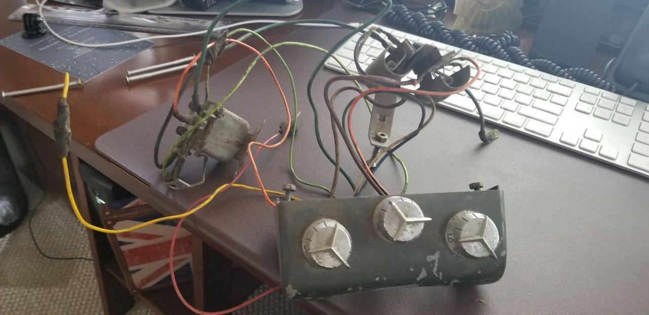
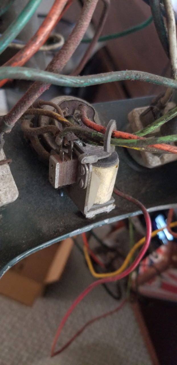
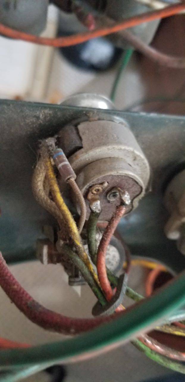
These photos might help with some of the questions. The power relay is mounted to the dash edge a few inches away from the control module as are the resistors for the blower speed change. As I recall the 4 wires from the control module area to the rear evaporator is in a loom that goes down the side of the tunnel similar to the way the loom for the rear power windows runs. I do not remember how the wire gets to the solenoid valve though. I think it is part of the main loom along with the heater blower motor wire but will not swear to that. Other than Dwight Heinmuller can't think of anyone else who might have an AC car that you could ask. If you email him he could probably tell you or even take a photo.
Note the power relay in this photo is the first or original style. It is similar to an R11 OD relay but with an extra terminal on the protected side of the fuse. Stude put out a bulletin saying stock was exhausted on that relay and a substitute with 3 terminals was to be used with a corresponding wiring change. No idea how many changed relays might be out there but the wiring change was minor and would not affect anything that would need to be changed in your loom.
Posted on: 2021/2/13 16:46
|
|||
|
Howard
|
||||
|
||||
|
Re: A Tale of Two Patricians
|
||||
|---|---|---|---|---|
|
Home away from home
|
Howard, that is excellent, thank you! I actually have a 1954 senior control panel which has been 3D scanned so it's all apart and difficult to know what goes where.
Posted on: 2021/2/13 18:20
|
|||
|
||||
|
Re: A Tale of Two Patricians
|
||||
|---|---|---|---|---|
|
Webmaster

|
I think there was only one A/C pod available. Even clippers I've seen with factory air have the same control panel with the senior style knobs. I've never seen one with junior knobs.
Posted on: 2021/2/13 20:28
|
|||
|
-BigKev
1954 Packard Clipper Deluxe Touring Sedan -> Registry | Project Blog 1937 Packard 115-C Convertible Coupe -> Registry | Project Blog |
||||
|
||||
|
Re: A Tale of Two Patricians
|
||||
|---|---|---|---|---|
|
Home away from home
|
The parts book lists different knobs for the non-1954 seniors but I've never seen them other than in photos such as this of a 1953 Clipper.
Attach file:  ACControls.jpg (33.88 KB) ACControls.jpg (33.88 KB)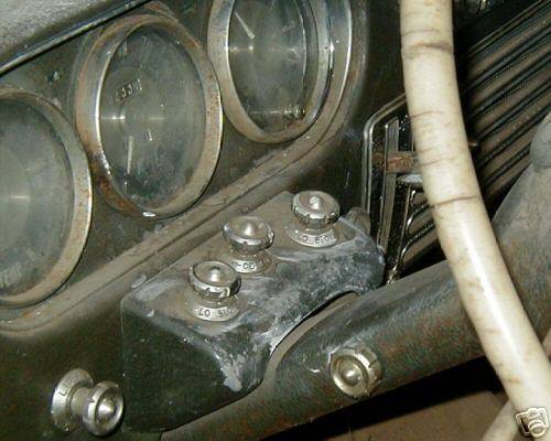
Posted on: 2021/2/13 20:39
|
|||
|
||||
|
Re: A Tale of Two Patricians
|
||||
|---|---|---|---|---|
|
Home away from home
|
To correct my earlier comment, the knobs for 1953 were the same as the junior knobs for 1954 and there were also 1954 senior knobs.
Are the knobs on the rear shelf the ones for opening the outside air inlets? Is it done through cables?
Posted on: 2021/2/13 20:49
|
|||
|
||||
|
Re: A Tale of Two Patricians
|
||||
|---|---|---|---|---|
|
Forum Ambassador
|
Quote:
Yes. Cadillac had a single knob which worked both inlets simultaneously but Packard had a separate knob for each side. The mechanism the knob attaches to that moves the Bowden cable is very much like the windshield wiper motor actuator located inside the steering column. Difference is that Instead of a straight length of wire with a washer on the end that fits in the slider on the wiper motor, the mechanism for the vents have a loop on the end of the cables to work a smaller version of the flapper valve like the heater and air vents in front use. That flapper is located inside the metal adapter tube that is attached to the return plenums. Attach file: inlet.jpg (143.62 KB)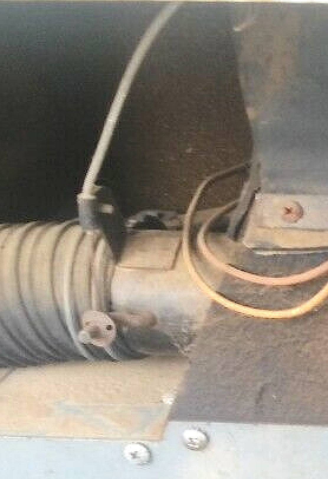
Posted on: 2021/2/13 21:11
|
|||
|
Howard
|
||||
|
||||


