|
Re: Vacation Car - 56 Patrician
|
||||
|---|---|---|---|---|
|
Home away from home

|
Quote:
Alright Howard, I was able to complete your tests using box 1 & box 3. Both had the same results: When touching either of the double terminals and taking them to ground I got movement from the motor. When touching either wires next to the green center wire I got movement from the motor. On box 2 still just dropped the rear end. WHICH!! After rereading your tests I decided to do some checking. The yellow terminal on this box is always grounded. That is not the case on the other two boxes. The other two boxes only have the yellow terminal closed to ground once the relay closes. So I believe this tells me the this terminal on box two was installed wrong making it always closed to ground. Which is why it will lower the rear of the car regardless of the position of the dash switch since that is always giving that solenoid ground. So. I cleaned all the contacts in all three boxes and was able to get movement at the relays on all of them. Only box two did the relays actually snapped closed with some force. I only got lazy movement on both relays on box one, and box three was able to snap one relay closed but the other one had lazy movement. So with that information I installed box three and was able to get the rear to rise and lower by rotating the rotating arm!! That is awesome! However… rotating in one direction I get this jack hammering sound coming from the solenoids, and very slow movement of the motor. While the other direction moved the motor with the problem. So I believe this means that the relay with the lazy movement isn’t getting enough contact which means the solenoid isn’t getting a good ground and causing it to have this jack hammering sound. Now this was done after I tried to move the contacts closer under the relay and re soldered the wires to and from that relay. So for what ever reason some of my relays are not moving like they should. Is there a way to fix that? It appears that box two would be my best bet if I can get the yellow terminal to only go to ground with movement of the relay. But I have two packards that utilize these boxes and would be nice to have working spares
Posted on: 2023/4/15 16:32
|
|||
|
||||
|
Re: Vacation Car - 56 Patrician
|
||||
|---|---|---|---|---|
|
Home away from home

|
I have not worked on my 1956 yet but I understand that the boxes were quite different for 1955. Is it possible that one of yours is that type?
Posted on: 2023/4/15 18:22
|
|||
|
||||
|
Re: Vacation Car - 56 Patrician
|
||||
|---|---|---|---|---|
|
Forum Ambassador

|
Quote:
I have not worked on my 1956 yet but I understand that the boxes were quite different for 1955. Is it possible that one of yours is that type? The switch operation and except for the bottom terminal area inside the box, are identical. The main difference between 55 and 56 boxes is external. 55 had 3 exposed screw terminals which could corrode when wet so for 56 they changed to bullet type terminals and enclosed them in a weathertight box. They also added two extra double contact tie point terminals in that enclosure to accommodate the change of limit switch type. A service bulletin was issued noting that when 55 switches ran out the 56 switch was to be used and a short pigtail needed to be ordered and spliced to the 55 loom to connect to the different style terminals. On your boxes, if cleaning the contacts did not work it almost sounds like you would be a candidate for a solid state switch conversion. Since the Pacific Northwest Region no longer lists them on their projects page I don't know if they still handle them or who else might. Believe the work was done on an exchange basis but maybe someone else knows a source. If not, the conversions seem to be relatively simple. Photos posted seem to show the original relays and bimetal elements were removed and two time delay relays used in place of the original components. I don't have a photo of the solid state box to post but Riki might have posted some on one of his project blogs. Since the conversion is so simple I know he was doing some research on available relays Amazon carries to find some that might work. Don't know if he actually found one or did a conversion yet but maybe if he sees this post he can answer. Amazon does have a pair of 10 second delay cube types that might work but without actually doing a conversion myself I cannot say for sure they would work or fit inside the switch box.
Posted on: 2023/4/15 18:35
|
|||
|
Howard
|
||||
|
||||
|
Re: Vacation Car - 56 Patrician
|
||||
|---|---|---|---|---|
|
Home away from home
|
One thing that can make relays and solenoids "chatter" and make a jackhammer sound is not having enough current available to operate them properly. A weak/discharged battery or a poor connection or ground or a corroded switch contact could cause it. In some cases, where a relay operates a motor or other high current device, if the power supply is inadequate, the relay will close, sending power to the device it operates, which then loads the circuit such that the relay starves for current and releases. When it releases, current demand drops and it closes again, repeating the cycle over and over, producing the stuttering or chattering sound. This may have nothing to do with your issue, but it's something to consider.
Posted on: 2023/4/15 19:17
|
|||
|
||||
|
Re: Vacation Car - 56 Patrician
|
||||
|---|---|---|---|---|
|
Home away from home
|
I have not got to try the timing relays out.
But no reason they would not work. The circuit board. A model train guy I know can make up a circuit board. Then gerber file it to a pcb manufacturers.. Pretty cheap.. But also. Was going to hit up hh56 about how to replace the solenoids with something solidstate.and heavy duty relays Edit. Picture Attach file:  20190119_144735.jpg (169.82 KB) 20190119_144735.jpg (169.82 KB)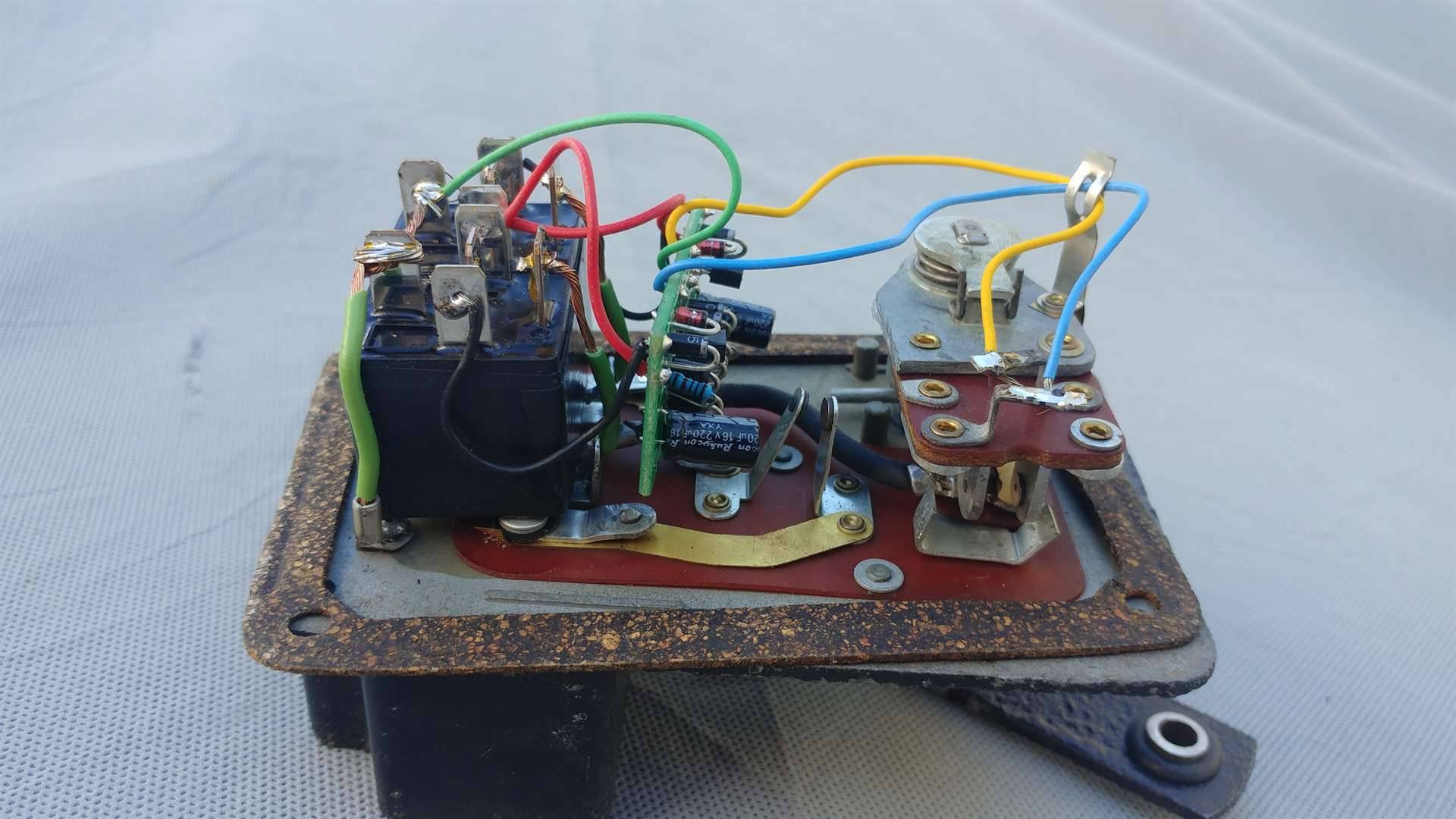
Posted on: 2023/4/16 2:35
|
|||
|
Riki
|
||||
|
||||
|
Re: Vacation Car - 56 Patrician
|
||||
|---|---|---|---|---|
|
Home away from home
|
Quote:
Quote:
This is all wonderful information thank you!! so if I want to get one of these working I got to start working on getting Box two fixed by finding out why the yellow terminal is always going to ground. R H, that doesnt look to bad to replicate. I can try and do something like that if you dont have the time and dont mind sharing the gerber file, wiring diagram, and component information.
Posted on: 2023/4/17 10:02
|
|||
|
||||
|
Re: Vacation Car - 56 Patrician
|
||||
|---|---|---|---|---|
|
Home away from home
|
I.ll have to ask him to .
Its just. 2. Timing circuits.. On the web many diagrams.. Of timing circuits. Its working in the relays. With the timing relays. You can get on amazon. They also have adjustable ones but are expensive. But its the same just figuring out the wiring. And I was going to put them under the hood. Just run wires from switch.
Posted on: 2023/4/17 17:20
|
|||
|
Riki
|
||||
|
||||
|
Re: Vacation Car - 56 Patrician
|
||||
|---|---|---|---|---|
|
Home away from home
|
Quote:
Okay, so I found this simple timing circuit: http://www.learningaboutelectronics.com/Articles/555-timer-delay-before-turn-on-circuit.php So the trigger would be from the rotating arm letting the switch know the car changed positions. Your input voltage would be from the green wire that is controlled by the dash switch. Your output would be going to the relay. Now how does the relay work (wiring it up) sending the ground signal to the limit switch?
Posted on: 2023/4/18 9:29
|
|||
|
||||
|
Re: Vacation Car - 56 Patrician
|
||||
|---|---|---|---|---|
|
Forum Ambassador
|
You might want to do a bit more research on what else will be needed in the circuit when using the 555 as the TL timer solution. As I recall, the 555 is somewhat sensitive and needs a fairly clean power supply or else operation becomes very erratic or chip doesn't work at all.
Auto electrical systems of that era are inherently "noisy" because of all the switches, coil and other ignition components, and even the generator brushes sparking. That activity is broadcast or directly connected to the same wiring used for voltage distribution so is picked up and carried all over. Evidence that by the various filter capacitors that need to be added at specific places to keep most of the electrical "noise" from being picked up and becoming static on the radio. You would probably need to add some conditioning directly to the power going into the chip. Also, in that diagram the the load is shown as only being an LED which typically needs on average about 10ma to work. I don't know offhand how much current the 555 can directly power but depending on the relay used, you will probably need to have the timer chip trigger a transistor stage with the transistor being capable of carrying the current needed for the relay coil. The transistor stage will require a few components and the relay coil might also need conditioning so the back emf when the magnetic field collapses is not sent back to the transistor and damages it. I went ahead and ordered a couple of stand alone timer relays that MIGHT work. Won't know for sure until they get here which should be tomorrow. If you can hold off a few days until I can test them it may be an easier solution. If they don't work then you can go to Riki's friend and see if he will make you a proper circuit assy or back to researching the 555 timer with only a bit of time wasted. For anyone interested, here is an example of what is meant by electrical noise as shown on an oscilloscope. The heavy center dark line is ground, the heavy line at the top of the square pulses is 12v. On a clean power supply those lines would be extremely straight and much narrower. Notice the roughness in these lines along with the small spikes above the 12v line and the very large ones in the dashed box below the ground line. That is noise and in this case is caused only by the instrument voltage regulator contacts operating. Imagine what all the other switches could do when added to what is from only one component. Solid state circuitry can not work with that kind of activity on the power supply so various means of conditioning input voltage is required.. Attach file: Instrument Regulator output waveform.jpg (48.83 KB)
Posted on: 2023/4/18 10:42
|
|||
|
Howard
|
||||
|
||||


