|
Re: Stewart's 1955 Packard 400
|
||||
|---|---|---|---|---|
|
Home away from home
|
Stewart
12+ or 12- ? dp
Posted on: 1/25 16:24
|
|||
|
||||
|
Re: Stewart's 1955 Packard 400
|
||||
|---|---|---|---|---|
|
Home away from home

|
Personally I would leave it stock unless you are doing something like adding A/C.
The charging system in these is perfectly fine when in adjustment and when you know the minor limitations. If you are having problems, a regulator adjustment or replacement is likely all that is required.
Posted on: 1/25 17:14
|
|||
|
'55 400. Needs aesthetic parts put back on, and electrical system sorted.
'55 Clipper Deluxe. Engine is stuck-ish. |
||||
|
||||
|
Re: Stewart's 1955 Packard 400
|
||||
|---|---|---|---|---|
|
Home away from home

|
It is a 12-volt, negative ground.
I would not mind leaving the generator in place as long as it charges the battery. With all the changes I am not sure it is set up correctly to do that. How does power flow to the battery?
Posted on: 1/25 21:14
|
|||
|
Stewart Ballard
|
||||
|
||||
|
Re: Stewart's 1955 Packard 400
|
||||
|---|---|---|---|---|
|
Forum Ambassador

|
When the engine starts and generator starts spinning a faint residual magnetism in the field coil poles of a properly polarized generator is enough for the armature to start producing a small low current voltage. That small voltage is enough to have the shunt winding bring in the cutout relay and when that relay energizes the battery is connected to the circuit. Once the battery connects, with the field coils also connected to the armature windings in the generator voltage then flows to the field coils so their strength is increased and generator starts putting out the voltage and current as determined by the regulator. The generator output voltage and current flow starts flowing back thru the closed cutout contacts to re-charge the battery. The series winding of cutout relay keeps the contacts solidly closed until generator speed changes and output falls.
When the engine is idling the generator output voltage falls to a lower level and may not be high enough to keep the cutout relay energized solidly. The relay connecting and disconnecting is what causes the flicker of the generator idiot light on those cars so equipped. On ammeter equipped cars there is not much of an indication of a low output other than the needle sits in the middle or dips slightly to the discharge side. A continued or large deflection to the discharge side indicates generator or regulator is not working or current requirements in the car are more than sometimes the generator or regulator can accommodate. When current demand is low the current and voltage sections of the regulator modulate the field coil strength to keep the output coming at the proper voltage but at a current level determined by demand. Here is a diagram of a typical generator charging circuit. Attach file:  Charging Circuit.JPG (164.65 KB) Charging Circuit.JPG (164.65 KB)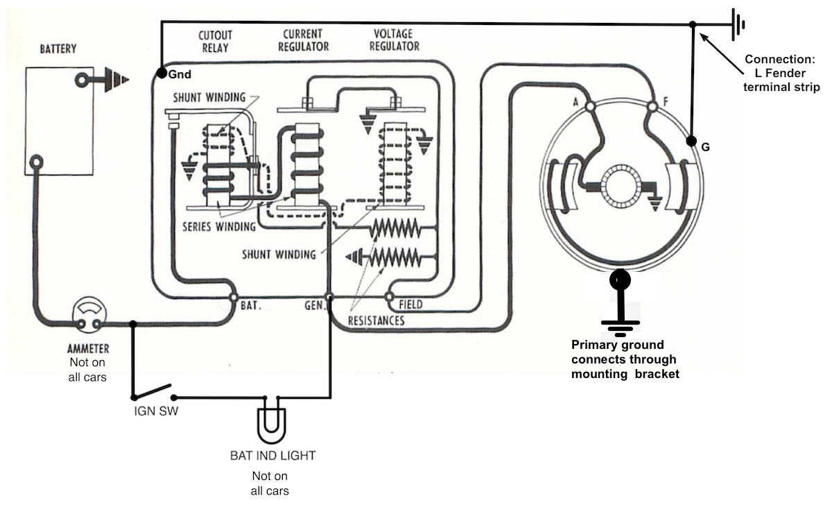
Posted on: 1/25 21:50
|
|||
|
Howard
|
||||
|
||||
|
Re: Stewart's 1955 Packard 400
|
||||
|---|---|---|---|---|
|
Home away from home
|
Stewart, I’ve added a few thoughts if you elect to change to an alternator. The 12- / 12+ question was asked to help guide discussion later in the process.
The ‘problem statement’ of swapping from a generator to an alternator has been done perhaps hundreds of thousands of times . . . well maybe not that many, but enough so there are few unknowns at this point. First let’s start at which brand of alternator to choose: All of the ‘big three’ products had unique to the brand alternators, but I would suggest the Delco units found on GM products. From a financial standpoint the 10SI or 12SI units are the smart choice (opinion). The difference between the two models is the self-cooling ability. The early 10SI units were cooling limited to about 60A output (likely twice the output of your generator). The 12SI added additional inlet area on the rear face of the unit, and the cooling fan that had a vane shroud. The 12SI output could be at least twice of the older design, or four times the output of your generator. The extra capacity was needed when continuous high current features were added. One of the first of these features was rear window heat. The alternator for cars so equipped had a higher output alternator than cars without the rear window heat. I don’t know of any ‘downside’ of having reserve current capacity. In the OEM configurations the capacity of the charging system is matched to the load that is expected to be continuous (with little positive margin). If all of the continuous loads are powered there is little left to charge the battery or operate the transient loads (horns). So if the headlights and heater blower loads are off, technically you’re operating with reserve capacity, therefore having a bit more won’t hurt (opinion). I think a 60 A 10SI alternator will be more than enough. The mounting of the 10SI and 12SI are identical, and there are many brackets that would be direct replacement for your generator mount. Mounting will not likely be a problem. Pulleys for most of the standard belt widths are available (and are easily changed), and there is a selection of pulley diameter available, so matching the alternator minimum speed should not be a problem. The next subject is whether you expect to find a replacement alternator if you’re away from home on some type of a tour. Since your car is 12-volt negative ground you have a pretty good chance of finding a replacement . . . 12-volt positive ground not so much. One more consideration, that is, whether the alternator is electrically similar to the OEM configuration, or a different wiring scheme is used. Finally, we’ve arrived at the ‘one-wire’ / ‘three-wire’ conversation. Both the 10SI and 12SI alternators are internally regulated . . . somewhat a standalone unit. These internal regulators come in several flavors that are referred to one-wire or three-wire. The OEM used the ‘three-wire’ scheme, but it wasn’t called that at the time. The first wire connection, normally a threaded post pointing straight aft, is the output of the alternator (BAT on your current regulator). Both 1 & 3 wire configurations will have the output pole. The next two connections are ¼ inch male blade connections and only apply to the 3-wire scheme. One of the connections has two functions; first it is the connection for an ‘idiot light’, while the second function is to provide external excitation to improve low speed alternator performance. The external excitation current is actually the current lighting the bulb, however there are GM designs that had a resistor in parallel with the bulb. I believe the design intent is to current limit the excitation to approximately 1 amp. The final ¼ inch male connection needs a bit of explanation. In the automotive industry there is sufficient motivation to match the design to meet the need with minimum margin. It the case of the charging system there was a desire to minimize the wire gauge size when possible, and the output of the alternator was subject to these pressures. GM (Delco-Remy being a division of same) made a lot of cars, with many different circuit lengths between the battery and alternator, and the scheme to regulate the alternators output to the battery voltage was invented. With the addition of one small circuit between the battery and the alternator the battery could be held at 13.4 volts (nominal) even with some variable voltage drop between the two. The corrector plug for the two-blade connection are available. If you value being able to maintain your car far from home, then wiring your car the same way GM did would be a plus. If you would like to monitor the system the minimum would be an ‘idiot light’, followed by either a voltmeter, or ammeter. For my 6+ cars I bought a few digital voltmeters on EBay and wired them to a plug appropriate for the cigar lighter socket. One of the cars has a light, while the other has an ammeter . . . both have the EBay voltmeters (easily removed when the critics arrive). Finally, if maintaining the correct under hood look is a consideration there are PowerMaster alternators that look almost like a generator. The 12-volt negative ground unit (they don’t make a 12+) is available with and without a connection for the ‘idiot light’. I have a 6+ PowerMaster on my ’48 (ammeter). I drilled the aft case to install a phony field winding connection, and added an Autolite generator tag completed the ‘look’. The only missing items are the ‘oil caps’, otherwise it’s an adequate facsimile. I left the voltage regulator on the firewall. It doesn’t do anything now, but as I think about it, that regulator didn’t do anything the last time in was trying to control the generator. I agree with the comments about the adequacy of the OEM generator equipped charging system until your continuous load exceeds 30A. If the OEM system is complete junk adding an alternator is an easy way to return the car to service while the availability and $$ of restoring the OEM system is being investigated/accomplished. My ’54 has the OEM system that is working just fine. When I purchased the ’48 I would say the OEM system was on its last legs a few years before I bought the car. You mentioned a Painless wiring harness. Is the car functioning now, or are you in the process of swapping the harness? If you’re installing the new harness, I would investigate what you would need if on day two you installed an alternator. As a minimum I think you’ll need a 8 – 10 gauge wire from the alternator output to the BAT connection on the regulator, and if it is a 3-wire alternator the ‘idiot light’ wire (I believe it’s tan) on the GEN (perhaps ARM) connection removed from the regulator and extended to the alternator. The other blade on the 3 wire is attached to either the battery or the large connection on the starter solenoid. The armature and field wires connected to the generator will be insulated and folded-back on the harness. I think all of that wire harness modification and additions could be added when needed. Since the alternators are internally regulated, I don’t believe the wire bonding the generator and regulator together is required but bonding the alternator housing to a ‘good ground’ would be a ‘best practice’ subject. dp
Posted on: 1/26 0:01
|
|||
|
||||
|
Re: Stewart's 1955 Packard 400
|
||||
|---|---|---|---|---|
|
Home away from home
|
Here is an overdue update.
It took more time on all the power windows stuff then I thought it would but I have them all wired up now. The rear regulator are to yet installed. I want to get the window seals installed first, then the glass and the regulators but the seals are on back order and its taking a few weeks to get them. The regulators are built and ready to go with the new motors. The motors for the front seat are installed. Once the window stuff is done I will start installing the interior. Speaking of the interior. I am told the last of the stuff will be done in the next couple weeks. He was having a hard time with the door panels due to the rot on my original panels. So I found a decent panel on ebay for him to use have a pattern for the new ones. He seems pleased with it. I still have a leak in the stupid power window pump. I tried the leak stop but its not working. I am going to have to remove the pump soon check it out. Last time I tried to run the engine it would not idle. I ended removing and rechecking the carb. While it was off the engine I got the TV cable installed for the 700 R4. Also installed the resonators so I could run the exhaust line to a near by window. All that took a couple months due to the cold. Then today I decided to just kick the engine over with the starting fluid. It started fine and as I waited for it to shut off I realized it was idling on its own so, that was exciting. I only let run a minute as its low on some fluids. In the last image you will see a new addition to the shop. Its a 72 Ford Bronco. It is not mine. I am a friend do some body work. He let it set in his driveway for 15 years so I talked him into hauling down here for me to work on. Hopefully, I will be be back soon with more updates. Attach file: 20240311_154152_resized.jpg (722.89 KB)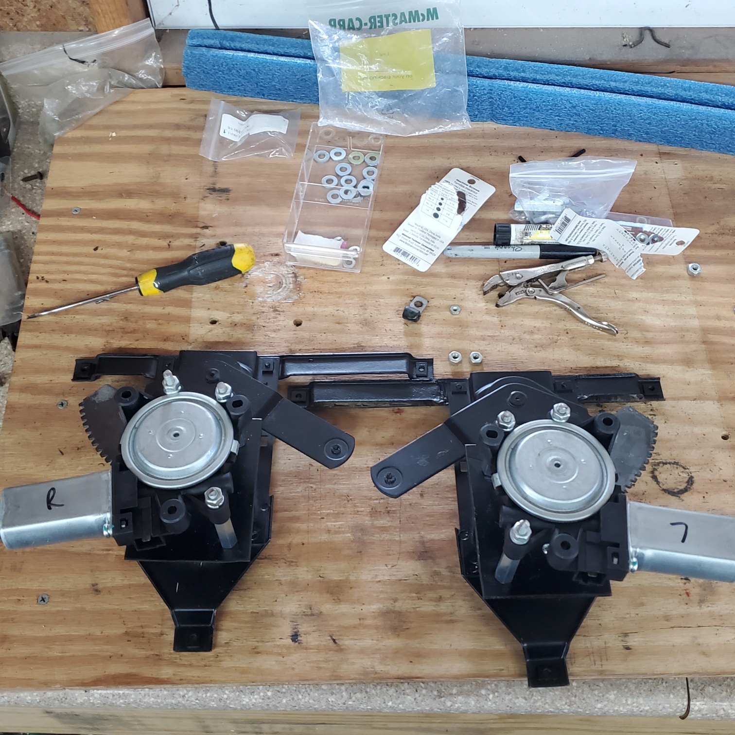 20240311_154218_resized.jpg (717.24 KB) 20240311_154218_resized.jpg (717.24 KB)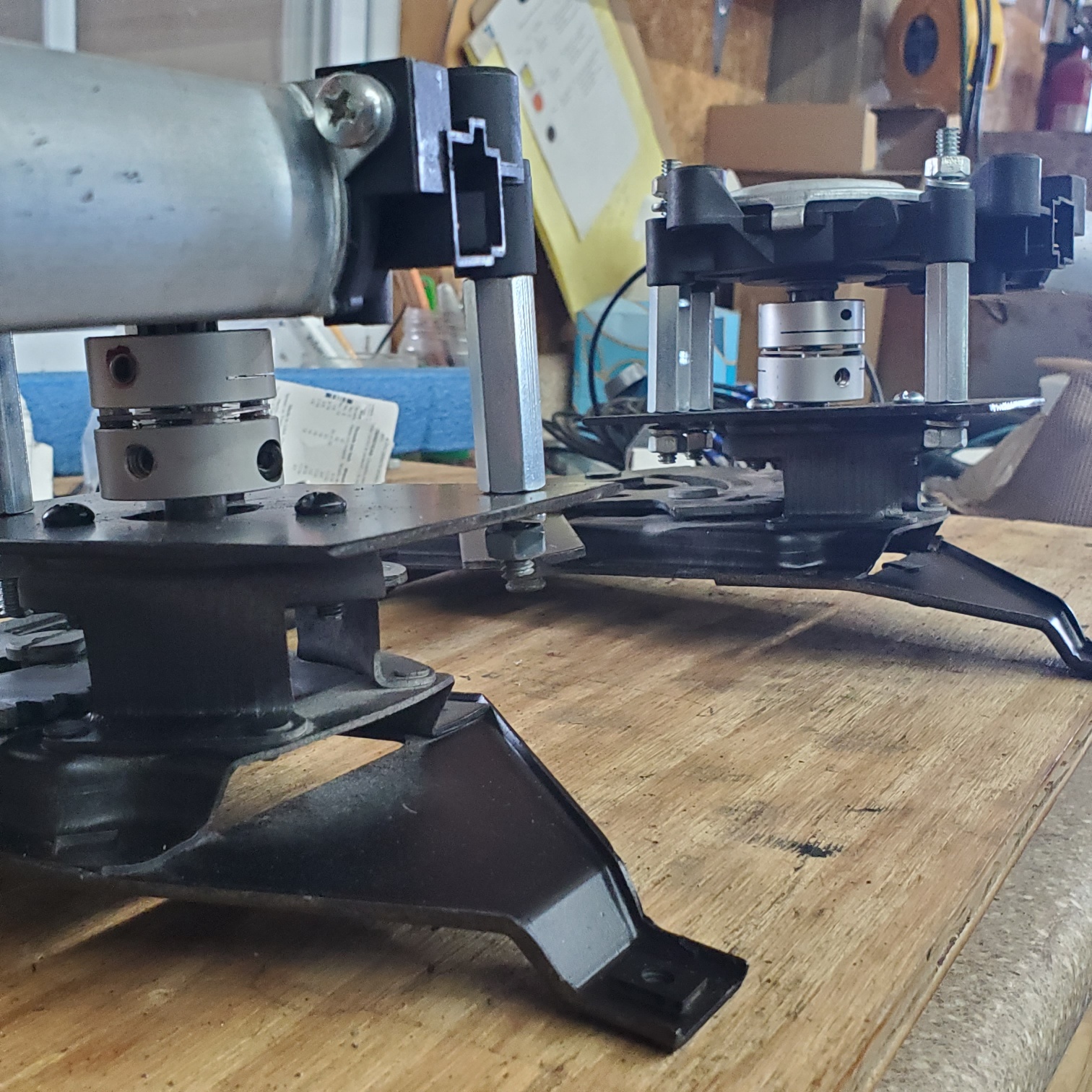 20240311_160253_resized.jpg (696.62 KB) 20240311_160253_resized.jpg (696.62 KB)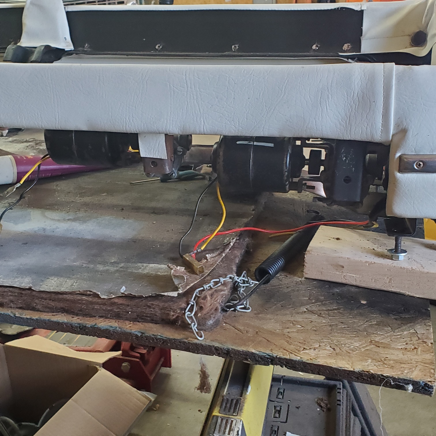 20240311_160259_resized.jpg (625.65 KB) 20240311_160259_resized.jpg (625.65 KB)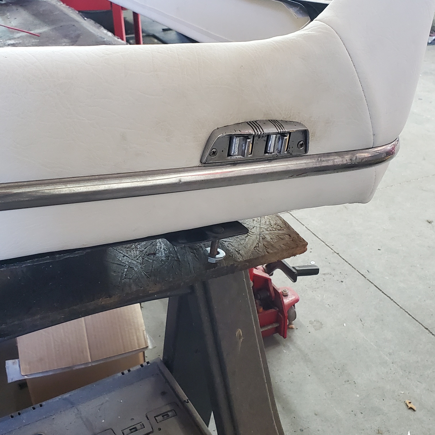 20240311_160234_resized.jpg (840.72 KB) 20240311_160234_resized.jpg (840.72 KB)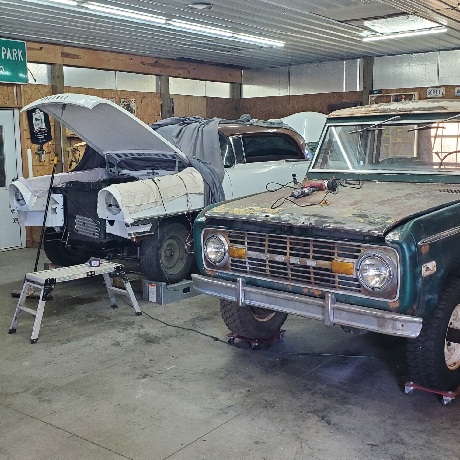
Posted on: 3/12 15:25
|
|||
|
Stewart Ballard
|
||||
|
||||
|
Re: Stewart's 1955 Packard 400
|
||||
|---|---|---|---|---|
|
Home away from home
|
Is there a drawing or something that shows the locations of the vacuum lines?
I have a couple of open ends on the engine and just wondering where they should lead.
Posted on: 3/14 18:11
|
|||
|
Stewart Ballard
|
||||
|
||||
|
Re: Stewart's 1955 Packard 400
|
||||
|---|---|---|---|---|
|
Forum Ambassador
|
No drawing I am aware of except a bit in parts book of WS wiper motor and washer but someone might be able to come up with photos of the engine. If not, on the carb there is a port on the side which connects to the small steel tube going to distributor advance can. On the rear of carb is another port where one of the ports of a brass block or a tee is connected. Second port of tee connects to a 1/4 steel tube which heads toward the right head and then bends back toward rear of engine where it kicks up an inch or two near the firewall. It is clamped to the head at the rear. The open end of the tube connects to a short rubber hose going to one of the side ports on the wiper balance valve. The other port on the block or tee connects to a check valve and then the 3/8 hose going to the brake booster.
If the stock crankcase vacuum pump is still installed, on the right side of the engine about in the middle and just above the oil pan is a port where an elbow is threaded in. That connects to a short length of 1/4 steel tubing. A few inches away from the elbow toward the rear is a check valve. The other side of the check valve connects to another section of 1/4 tubing which continues to the rear where the tube again kicks up a few inches near the firewall. Another piece of rubber tube connects to the second port on the side of the balance valve. If the engine has the Olds or PI pump mod that eliminates the aux vacuum pump the 1/4 line is disconnected and block port is plugged. Make sure the now unused port or tube on the balance valve is also plugged unless you are replacing the crankcase pump with something else and visually want to use the abandoned line to keep the vacuum supply more or less original looking. Attach file: balance valve.jpg (156.47 KB)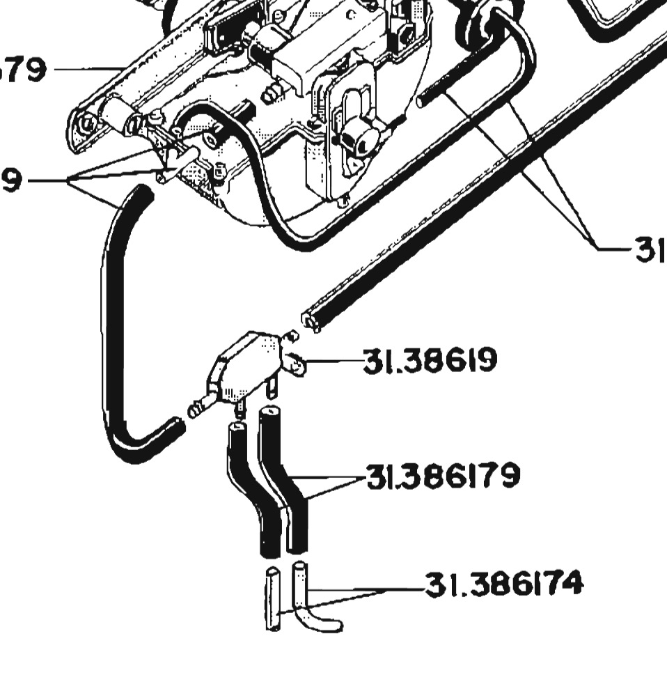
Posted on: 3/14 18:57
|
|||
|
Howard
|
||||
|
||||
|
Re: Stewart's 1955 Packard 400
|
||||
|---|---|---|---|---|
|
Home away from home
|
Stewart, here is the drawing from the Instruments section. It is slightly clearer in some ways. Along with Howard's comprehensive explanation I think everything has been disambiguated.
 My 400 engine has the Olds pump, but I could get some pics from my Clipper engine probably next weekend. And here is the part book drawing for the wipers:https://packardinfo.com/xoops/html/modules/partslist/viewplate.php?cat=11&PlateNumber=42&partslist=1955-1956 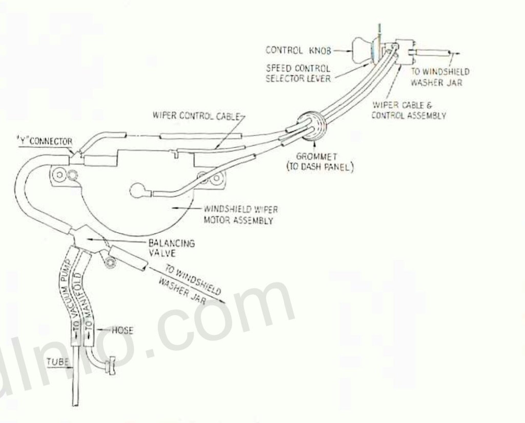
Posted on: 3/15 2:03
|
|||
|
'55 400. Needs aesthetic parts put back on, and electrical system sorted.
'55 Clipper Deluxe. Engine is stuck-ish. |
||||
|
||||


