|
Re: Alternator & Ammeter
|
||||
|---|---|---|---|---|
|
Forum Ambassador

|
"Thanks Mal, You're a whizz at this game"
Not really Peter, it's right at the limit of my ability. And only because someone else posted, fairly early in the piece, how to do that!
Posted on: 2016/6/10 4:44
|
|||
|
Mal
/o[]o\ ====  Bowral, Southern Highlands of NSW, Australia "Out of chaos comes order" - Nietzsche. 1938 Eight Touring Sedan - SOLD 1941 One-Twenty Club Coupe - SOLD 1948 Super Eight Limo, chassis RHD - SOLD 1950 Eight Touring Sedan - SOLD What's this?  Put your Packard in the Packard Vehicle Registry! Here's how! Any questions - PM or email me at ozstatman@gmail.com |
||||
|
||||
|
Re: Alternator & Ammeter
|
||||
|---|---|---|---|---|
|
Home away from home

|
G'day Men (don't know if I should be using that term these days),
Today I had the setup inspected by an auto elec and he said the way it was wired is fine and the alternator is charging correctly. When asked about the ammeter he essentially said the same as Howard - if I didn't mind the needle deflection then it was quite safe to leave as is. He thought I possibly could have gotten away with connecting the alternator to the red wire out of the old regulator, but agreed the guage size of the old wires could be a problem under full electrical load. It would be better however, to leave this wire connected to the regulator as it's now receiving current flowing in the opposite direction, so is "hot". The regulator still remains inactive. Regarding this wire, he thought that the ammeter must have some sort of shunt behind it, but I told him that if it does have one it must be internal as I could see nothing attached behind the ammeter, other than two red wires which look of similar guage to the red regulator wire. So, I have now decided to leave it all as is and keep an eye on the charge rate via the plug-in voltmeter. One other thing we spoke about was headlights. I had previously installed halogens and was concerned about the heat which probably would be generated when switched on, especially high beam. I explained that I had checked the wiring behind one of the headlights a couple of days ago and the cloth covering on the wires was disintegrating. We agreed that the headlights should be rewired, through a relay, and he'll be doing that in about a week's time. Cheers, John
Posted on: 2016/6/24 22:50
|
|||
|
||||
|
Re: Alternator & Ammeter
|
||||
|---|---|---|---|---|
|
Home away from home
|
Hello John and G'day to you to. I would agree with John that it is necessary to fit relays to the 56 Patrician headlight wiring system. I had the bi-metal relay on the headlight switch go off on mine a few times with the original wiring loom, so I used the headlight switch to power relays fitted adjacent to the headlight junction box. No more power-outs and less stress on the old wiring harness. However I would urge possible converts to an alternator to use a 45 amp unit and wire through the ammeter. I am not using this system through my 38-327 R6, using a 45 amp 12V alternator, and the ammeter gets pretty radically deflected with 130W headlights, parking lights etc on the discharge side of the meter. This does not happen with the Patrician. I am going to change the 38 Richards to using the Regulator output and have a balanced CHG/DISCHARGE meter as on the Patrician. PT
Posted on: 2016/6/25 2:52
|
|||
|
I like people, Packards and old motorbikes
|
||||
|
||||
|
Re: Alternator & Ammeter
|
||||
|---|---|---|---|---|
|
Forum Ambassador

|
I've added headlight relays on several cars now and this circuit seems to work well. Different relays and a different size breaker is all that is needed to use the same circuit on 6 or 12v cars. I went with a 30 amp breaker on 6v cars and 20 on 12v since that is what Packard used. Without the other lights normally fed by the headlight switch in the circuit, the breaker is probably a bit over sized on both but did it to be consistent.
The V8s are a bit more involved because the original loom is split and goes to junction blocks on both fenders. When I did mine I left the original loom connected but no longer used on the old terminal srtrip on right fender. Added another strip that was semi hidden and re-connected the short cable feeding the light to the new strip. Used some empty factory holes and placed the relay package on the left side where it was kind of hidden but still accessible. Location makes it easy to get relay signals from the original left fender strip and keep the new feed wire and breaker on same side as battery connection at solenoid.. A terminal strip on the module is to connect the cable to left headlight along with a new rubber covered cable as was done on previous Packards to power the right headlight via the new hidden terminals on that side. The 47 was much easier since there was only one strip. Made a bracket and used a factory hole to place the relays and a new headlight cable connection strip where everything was convenient but still kind of out of the way. Making an easily removed module for the package and keeping original wiring intact lets the cars quickly revert to stock if the next owner wishes. The relays are the only thing powered off the old headlight and dimmer switches. Schematic shows the basic circuit with 6v components and single terminal strip. That module has wire colors more in line with factory wire colors for the 47. V8s have slightly different colors and layout. Modules are shown mounted in a 56 and 47. Attach file:  (65.30 KB) (65.30 KB)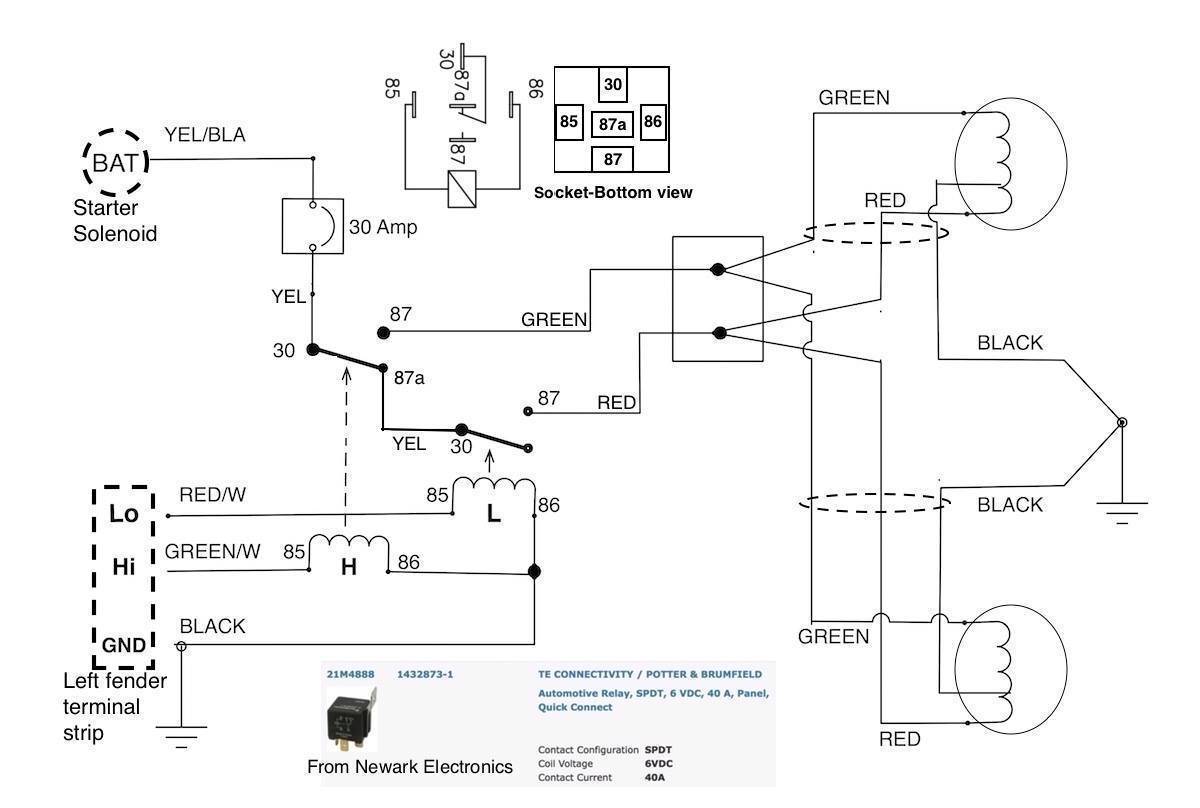 (45.71 KB) (45.71 KB)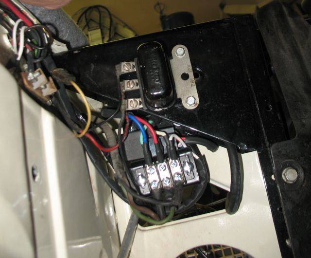 (40.25 KB) (40.25 KB)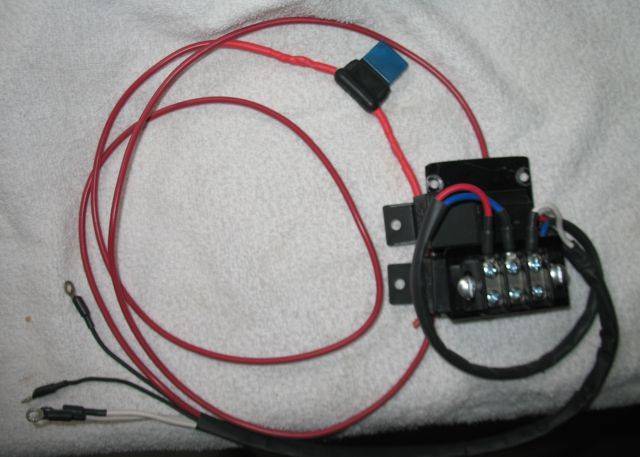 (118.56 KB) (118.56 KB)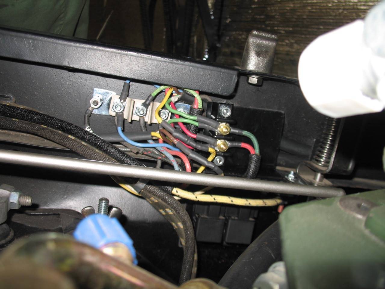 (95.06 KB) (95.06 KB)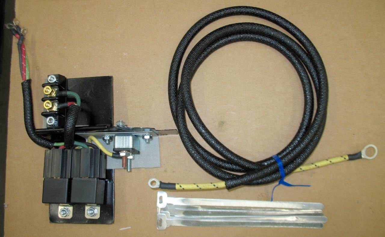
Posted on: 2016/6/25 9:07
|
|||
|
Howard
|
||||
|
||||


