|
Re: Power Antenna Wiring
|
||||
|---|---|---|---|---|
|
Home away from home

|
I can't be sure, but post #6 by Cli55er in his "Antenna won't go down" thread seems to describe a similar splice that I have.
Posted on: 2008/12/20 12:53
|
|||
|
||||
|
Re: Power Antenna Wiring
|
||||
|---|---|---|---|---|
|
Webmaster

|
A easy way to test the motor is to connect one of the motor wires to a power source, and then ground motor casing. That should make the motor spin in one direction. The unhooking that first wire, and connecting only the second wire to power should make the motor spin the other direction. Just make sure both wires are not connected to power at the same time.
If the motor fails to work in any direction, then you got a bad motor.
Posted on: 2008/12/20 13:04
|
|||
|
-BigKev
1954 Packard Clipper Deluxe Touring Sedan -> Registry | Project Blog 1937 Packard 115-C Convertible Coupe -> Registry | Project Blog |
||||
|
||||
|
Re: Power Antenna Wiring
|
||||
|---|---|---|---|---|
|
Home away from home
|
Never mind. I found the grommet that holds back shafts into place. It fell when I disassembled. I hope we're in business, now. Will put back together and re-post.
Posted on: 2008/12/20 13:51
|
|||
|
||||
|
Re: Power Antenna Wiring
|
||||
|---|---|---|---|---|
|
Forum Ambassador

|
Good show. You beat me to it as I just took a look at one to see what was missing. Also found a bulletin showing the rear type I mentioned earlier shown as used on the front. Anyway, here are a few photos for others that might be in same boat sometime.
The switch is interesting as it looks like there are wires attached directly to switch instead of bullet connectors and the connectors then on wires-- Have seen that somewhere but memory fails right now. Almost makes me think it was for an earlier 51-4 as the schematics show the extra terminal--except if that the case, knob shouldn't fit. Attach file:  (26.24 KB) (26.24 KB)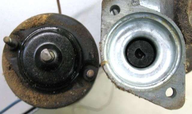 (20.35 KB) (20.35 KB)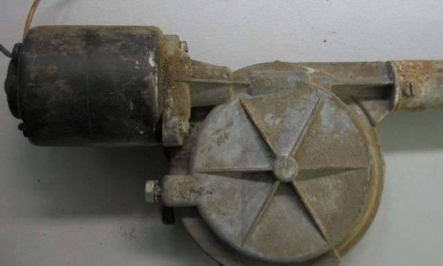 (80.69 KB) (80.69 KB) (10.68 KB) (10.68 KB)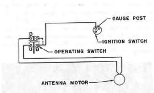
Posted on: 2008/12/20 14:09
|
|||
|
||||
|
Re: Power Antenna Wiring
|
||||
|---|---|---|---|---|
|
Home away from home
|
Houston, we have lift off!
For everyone who helped, thank you so much! I love fixing things! All said and done, I believe the wire from the knob that fell off was not the real culprit as I had no motor engagement even with the "lowering" wire attached. When I blew the fuse, I figured the motor had to be mounted and/or the ground wire from the power wires/antenna bundle inside the fender had to be attached to the ground post. I can't say I 100% understand, but my guess was the ground was required for power and it was not grounded right. So, the antenna goes down until it protrudes above fender maybe 10". It goes up - way, way up! The thing must be 5' long! There is not an automatic shut-off when it reaches max height or complete lowering. I can continue to push or pull the nob and hear motor continuing beyond max height or lowering. Is this normal? I have fear of breaking something (i.e. the nylon cable) by accidentally pushing or pulling the knob too long. P.S. HH, I still don't know where you are getting these bulletins and schematics. I looked in the bulletins section, and under accessories. There are references to a few bulletins regarding the antenna, but there are no links to those. I must be missing an entire section of this site.
Posted on: 2008/12/20 14:24
|
|||
|
||||
|
Re: Power Antenna Wiring
|
||||
|---|---|---|---|---|
|
Forum Ambassador
|
You are correct--there is no automatic shutoff so when it stops or you hear the motor change pitch let off. Continued motor action will either grind a crescent shaped hole in the type with the flat nylon which makes it stop at that point until you push or pull antenna mast past the bad spot or will break nylon entirely. Either results in no workee. The type you are working on has "teeth" inside the round part that pulls or pushes the nylon which can abrade or break it.
Except for the Studebaker bulletin portion I just posted above, (which I just found in a Stude manual and admittedly we are a bit short on since there apparently is a lack of site members with those particular pieces available) everything is on site here. The schematics all came from the service manuals. I have most of them on my computer also which makes it easy to grab a page or just a piece of whatever am talking about for posting.
Posted on: 2008/12/20 14:53
|
|||
|
||||
|
Re: Power Antenna Wiring
|
||||
|---|---|---|---|---|
|
Webmaster
|
Every Packard owner should download at least 3 documents to have on their computers for quick reference:
1) The entire Service Manual for their particular series 2) The Parts List (aka Part Manuals) for the exploded parts diagrams 3) Owner's Manual to explain operation and simple maintenance. Once you have those, then the Service Techincal Bulletins (STBs) , and the Service Counselors (SCs) are the next essential resource for any running changes.
Posted on: 2008/12/21 19:13
|
|||
|
-BigKev
1954 Packard Clipper Deluxe Touring Sedan -> Registry | Project Blog 1937 Packard 115-C Convertible Coupe -> Registry | Project Blog |
||||
|
||||
|
Re: Power Antenna Wiring
|
||||
|---|---|---|---|---|
|
Home away from home
|
Well, my antenna worked all day yesterday, but not this morning. I am going to check the fuse later, but I feel confident the fuse is fine, as it is hooked up to the wiper fuse, and the wipers operate.
This intermittency is a repeat of the original problem. When I took the antenna out and didn't notice anything wrong, I put it back and then, sort of like serendipity, it just works. I don't know why it would be intermittent. When it works, the motor sounds good, and the antenna operates smoothly.
Posted on: 2008/12/22 11:20
|
|||
|
||||
|
Re: Power Antenna Wiring
|
||||
|---|---|---|---|---|
|
Forum Ambassador

|
I don't use the antennas often on my 56 Caribbean (dual antennas) but whether its because there are two motors, or perhaps a bit too much friction, the fuse would occasionally blow just before they reached the top or bottom. It's not a good idea to use a higher amperage fuse, so I simply replaced the standard fuse with a "slow blow" variety of the same amperage. Never a problem since; you might try that if you find the problem is the fuse again.
If you have an ammeter, you might consider putting in line with the motor (ammeters always go in series, voltmeters always in parallel) and just measuring the current draw.
Posted on: 2008/12/22 11:24
|
|||
|
||||


