|
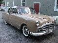
Re: Vacation Car - 56 Patrician
|
||||
|---|---|---|---|---|
|
Home away from home

|
Quote:
Yes I can wait! The fact that I know what needs done is a big weight lifted off my chest. The next step for this car is replacing suspension bushings that I hope to start in the next week or so.
Posted on: 2023/4/18 12:12
|
|||
|
||||
|
Re: Vacation Car - 56 Patrician
|
||||
|---|---|---|---|---|
|
Home away from home

|
If someone has the Gerber file or even a schematic with component listing, a solid state controller would be something I would love to make for my 1956!
Posted on: 2023/4/18 12:35
|
|||
|
||||
|
Re: Vacation Car - 56 Patrician
|
||||
|---|---|---|---|---|
|
Home away from home
|
I.ll have to look at other picture
I don't think a 555 is used
Posted on: 2023/4/18 15:53
|
|||
|
Riki
|
||||
|
||||
|
Re: Vacation Car - 56 Patrician
|
||||
|---|---|---|---|---|
|
Home away from home
|
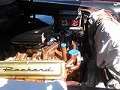
Here is the relays I bought
Attach file:  20230418_135520_(1).jpg (344.61 KB) 20230418_135520_(1).jpg (344.61 KB)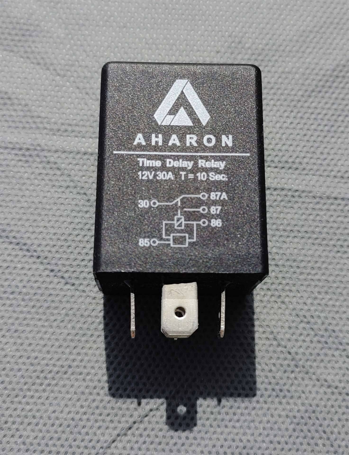
Posted on: 2023/4/18 15:56
|
|||
|
Riki
|
||||
|
||||
|
Re: Vacation Car - 56 Patrician
|
||||
|---|---|---|---|---|
|
Home away from home
|
What the circuit board does
It uses transistors as a switch. Which starts the timing . Only thing on the board are diodes and resistors. And 2 capacitors.. One for each timing circuit.
Posted on: 2023/4/19 2:17
|
|||
|
Riki
|
||||
|
||||
|
Re: Vacation Car - 56 Patrician
|
||||
|---|---|---|---|---|
|
Forum Ambassador

|
Quote:
Ross, this is an interesting idea. A question would be how many would consider that approach and want to eliminate or bypass the solenoids rather than just having the relays work them as the conversions are now made. In a 55 bulletin Packard said the motor under normal conditions should pull about 17 amps and installed an inline fuse of 20 amps. In 56 they upped the fuse to 30 amps. The contacts in the cube type relays Riki and I are considering are rated at 30 amps. One question with relays as the main switching device would be if the motor stalled and pulled max current which would go first -- the fuse or would the relay contacts weld and then the fuse decide to blow. The small safety margin might be a consideration. Any larger relays will be expensive and harder to package For a 56 making the TD relays external and wiring them would be relatively easy. For a 55, because of the limit switch configuration, maybe a bit harder. In either case, the control box would still need to be opened and the original bimetal timer and relays removed or at least bypassed. Cost wise, with everything needed cube type TD relays would probably be less than the reworked solid state boxes alone since the relays and additional things needed are not that expensive. One thing I am concerned about with mounting the TD relays inside the control box is space and placing them in a weathertight box mounted on top of the control switch might be feasible no matter if they still operate the solenoids or work the motor directly. Pin layout is the same as the typical cube relay but the case is longer and it requires mostly gutting the control box to fit them inside. The conversions with timer board must use a much smaller relay. No idea about the contact rating on those relays. Anyone have comments on either approach and whether relays should be in or could be tolerated if outside the control box??
Posted on: 2023/4/19 12:03
|
|||
|
Howard
|
||||
|
||||
|
Re: Vacation Car - 56 Patrician
|
||||
|---|---|---|---|---|
|
Home away from home
|
As one who prefers authenticity but is not adverse to hidden modernizations, solid state innards would be the way to go. Of course, it would take two different designs for 1955 and 1956 due to the former being positive ground which has been the issue I have with the solid state voltage regulator I’m working on.
Posted on: 2023/4/19 14:33
|
|||
|
||||
|
Re: Vacation Car - 56 Patrician
|
||||
|---|---|---|---|---|
|
Forum Ambassador
|
Agree on the need for a polarity difference . The nice thing about using the relays is all it will take is swapping two wires on each relay to have the proper configuration.
What I am trying to do now is figure out the best location for the relays. Ideally the conversion would be simple enough that it could be DIY for those who cannot or do not want to buy the ready made units. Not sure DIY will be an option if they are mounted inside due to the space needs of the relays. Speaking of ready mades, since the project page and info on the switches is completely missing from the PNW region website I am not sure where or if the exchange conversions are even available anymore to refer if someone is in need of one.
Posted on: 2023/4/19 15:36
|
|||
|
Howard
|
||||
|
||||
|
Re: Vacation Car - 56 Patrician
|
||||
|---|---|---|---|---|
|
Home away from home
|
The picture I posted
I didn't notice that a contact is missing. After these years I noticed it. Little pissed off. Since I sent an all around good box.. Not sure if I want to.. But Cutting the relays of out the plastic cover. Might work for inside the box. The ones they used are same size. They glue relays so the contacts are up. I would go Ross's route. With circuit breakers. Resetting type. Maybe..
Posted on: 2023/4/20 9:37
|
|||
|
Riki
|
||||
|
||||


