|
Re: 1937 Battery Draw
|
||||
|---|---|---|---|---|
|
Home away from home

|
Hmm I can't see anything from that. Can you send a picture of the bottom of it?
Posted on: 2022/10/30 13:17
|
|||
|
'55 400. Needs aesthetic parts put back on, and electrical system sorted.
'55 Clipper Deluxe. Engine is stuck-ish. |
||||
|
||||
|
Re: 1937 Battery Draw
|
||||
|---|---|---|---|---|
|
Home away from home
|
Here are two pictures, one of the bottom and one of the top again but at an angle showing the relays. The cut out relay is at the bottom of the second picture.
Again, thanks. Attach file:  VRR4005A Voltage Regulator Bottom.JPG (364.44 KB) VRR4005A Voltage Regulator Bottom.JPG (364.44 KB)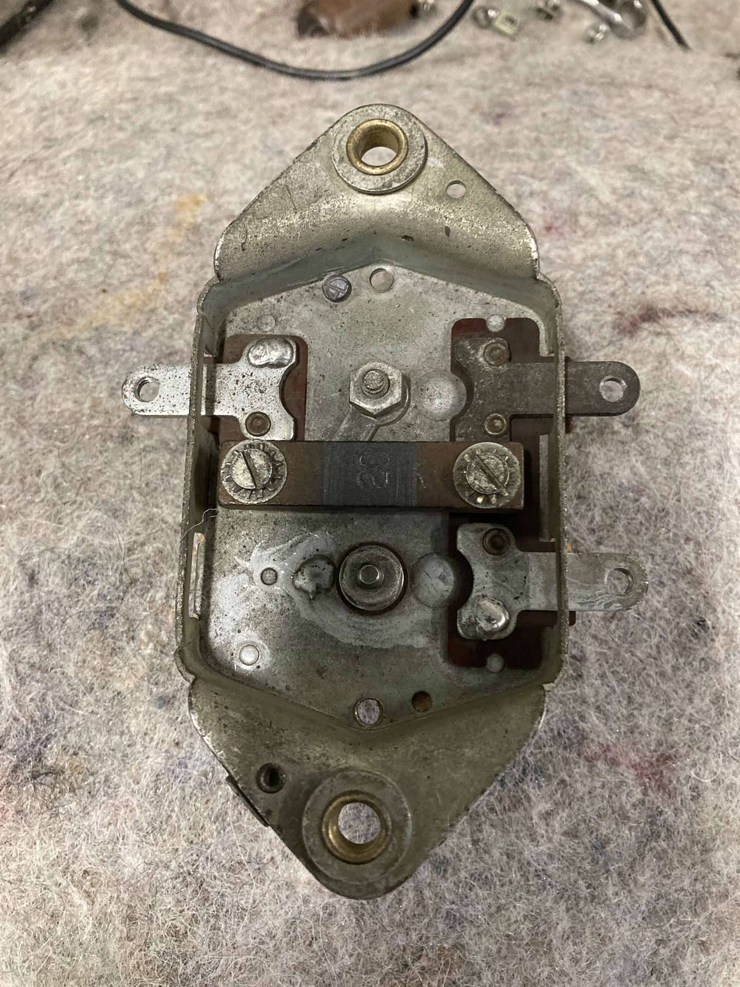 VRR4005A Voltage Regulator Top.JPG (231.47 KB) VRR4005A Voltage Regulator Top.JPG (231.47 KB)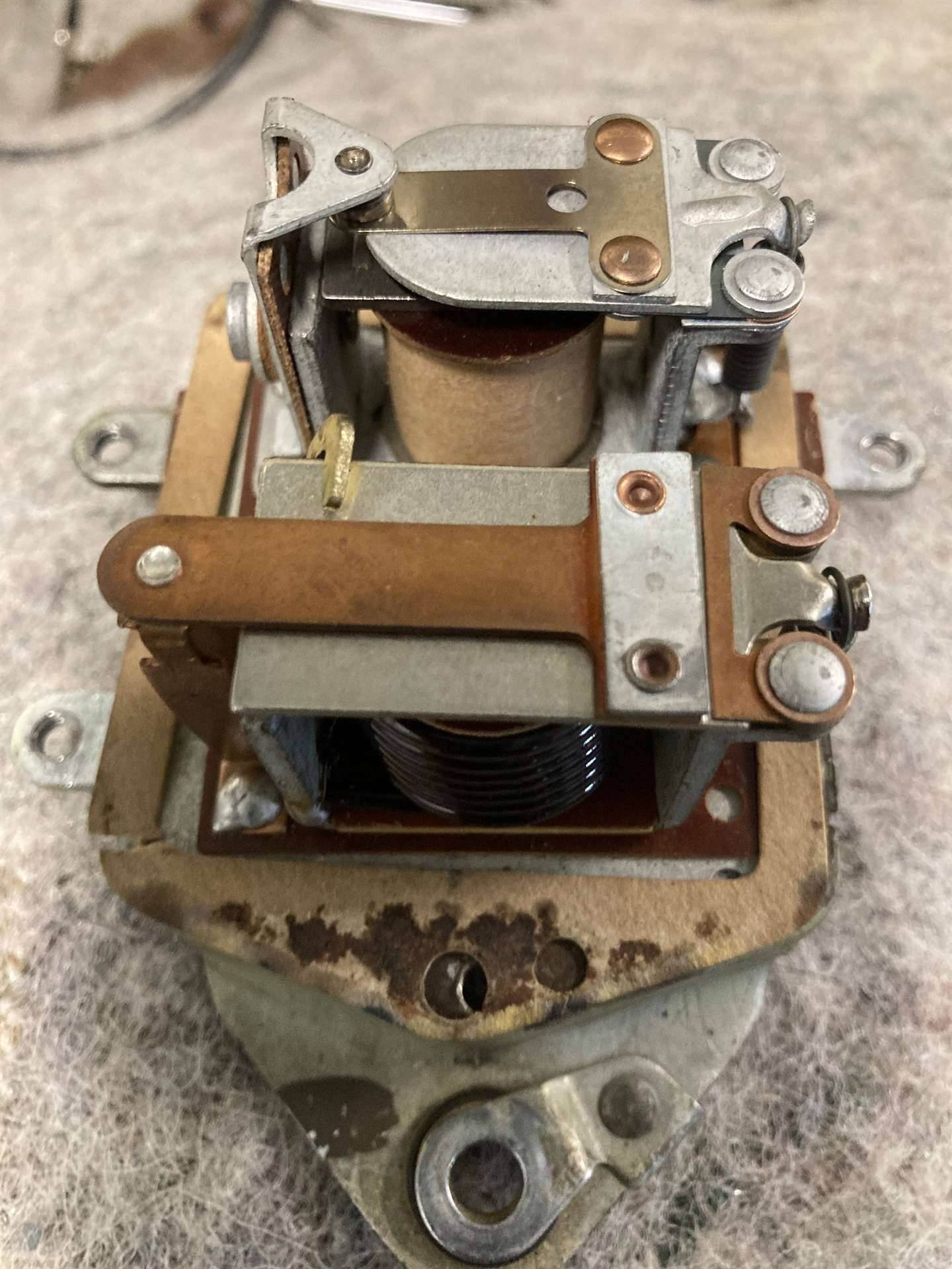
Posted on: 2022/10/30 13:28
|
|||
|
Roger Howe
Whitewright, TX 1937 120C Touring Sedan |
||||
|
||||
|
Re: 1937 Battery Draw
|
||||
|---|---|---|---|---|
|
Home away from home
|
I have another question for you. Which line is supposed to open the current relay, the one labeled Gen or the one labeled Fld?? If I knew that, I might have this solved for I suspect I had them switched because my ammeter still did not show any charging current to the battery.
Thanks.
Posted on: 2022/10/30 13:42
|
|||
|
Roger Howe
Whitewright, TX 1937 120C Touring Sedan |
||||
|
||||
|
Re: 1937 Battery Draw
|
||||
|---|---|---|---|---|
|
Home away from home

|
If you take the terminal screws off, are the terminal tabs stamped under those?
Posted on: 2022/10/30 14:31
|
|||
|
||||
|
Re: 1937 Battery Draw
|
||||
|---|---|---|---|---|
|
Forum Ambassador

|
When the regulator is just sitting there should be an open contact on one coil assy and a closed contact on the other. The battery terminal will be connected to one side of the open contact. Whether it is the fixed contact or the moving contact depends on how the regulator is constructed but with the regulator just sitting that single contact is the only thing the battery terminal will be connected to so voltage can go no farther. You can use an ohmmeter with one side connected to the BAT terminal and use the probe to find that contact. Just sitting, the BAT terminal should connect to a single contact and nowhere else in the regulator.
The way the charging circuit works is when the generator starts turning there is a slight bit of residual magnetism in the generator field pole shoes. That small magnetism is just enough to enable the generator to excite and put out a small voltage and current on the armature terminal. That voltage is supplied to the regulator and enters on the ARM (or GEN) terminal and due to a shunt winding on the cutout coil is enough to bring in the cutout relay. When the cutout relay closes it connects the battery to the other components in the regulator and also back to the ARM terminal. The battery is then stronger than the small voltage coming from the generator so it goes back to the generator and the way the generator is wired internally the battery can provide battery voltage to one side of the field coil. On two brush generators it is via a direct connection with the field coil but on third brush generators battery voltage needs to go thru a portion of the armature windings before leaving on the third brush and getting to the field coil. The other side of the field coil is connected to the regulator FLD terminal which is going to the closed contact the other coil operates. With one side of the closed contact connected to ground and voltage provided by the battery thru the generator field coil on the other end, the field coil gets fully magnetized and enables the generator to produce a high voltage and current. The generator output voltage is now stronger than the battery so it goes back to the regulator and battery and the regulator can also start working. There is another coil on the cutout relay which the ARM terminal now supplies to reinforce and keep the cutout relay closed. The gaps and spring tensions on the armature of the second coil or regulator side setup provide a balancing strength to provide the regulation. If the generator is putting out too much voltage a coil will be stronger than the spring so the contact will be pulled open. This immediately opens the field coil to ground but puts a resistor in the circuit which reduces the magnetic strength so generator output is lowered. When the output is low enough the spring can pull the contact closed again and full output is re-enabled. It then becomes a rapid vibrating and balancing act between coil and spring strengths which keeps the generator voltage output at a fairly constant level. To regulate the current, in addition to the coil operated by voltage there is a second coil also on the normally closed contact side which is fed from the ARM terminal. Too much current will give strength to that coil so the opening of the contact action to put resistance in the circuit repeats and current is regulated. The entire 2 relay assy is a balancing act between voltage and current but to provide better regulation the later regulators separated the voltage and current functions by adding a third coil and contact in the resistance circuit. By using a second resistor and a feedback circuit the current output operation was made more precise. You can probably determine which terminal is which by an ohmmeter. When the regulator sitting and disconnected: BAT will go to only one side of the open contact on the cutout relay. ARM will go to the other side and will probably be able to be found at other places in the regulator. FLD will go to one side of the normally closed contact on the other coil assy and with the ohmmeter between the FLD terminal and ground, with the contact closed there should be a very low -- almost 0 ohms -- resistance. When you push down on the armature to open the contact the ohmmeter reading should jump up to the neighborhood of 20 ohms.
Posted on: 2022/10/30 15:21
|
|||
|
Howard
|
||||
|
||||
|
Re: 1937 Battery Draw
|
||||
|---|---|---|---|---|
|
Home away from home
|
This is a two-relay Delco-Remy diagram but should also be typical of your Autolite. The Field terminal, as I recall and shown at the right here, is the one at the top when they are separated as they are on yours while the other two are as shown.
You probably already have the tag that should have come with your VRR4005A with some details. Attach file:  5662D7B4-C9CA-4D1E-8721-3E5719613C92.jpeg (155.77 KB) 5662D7B4-C9CA-4D1E-8721-3E5719613C92.jpeg (155.77 KB)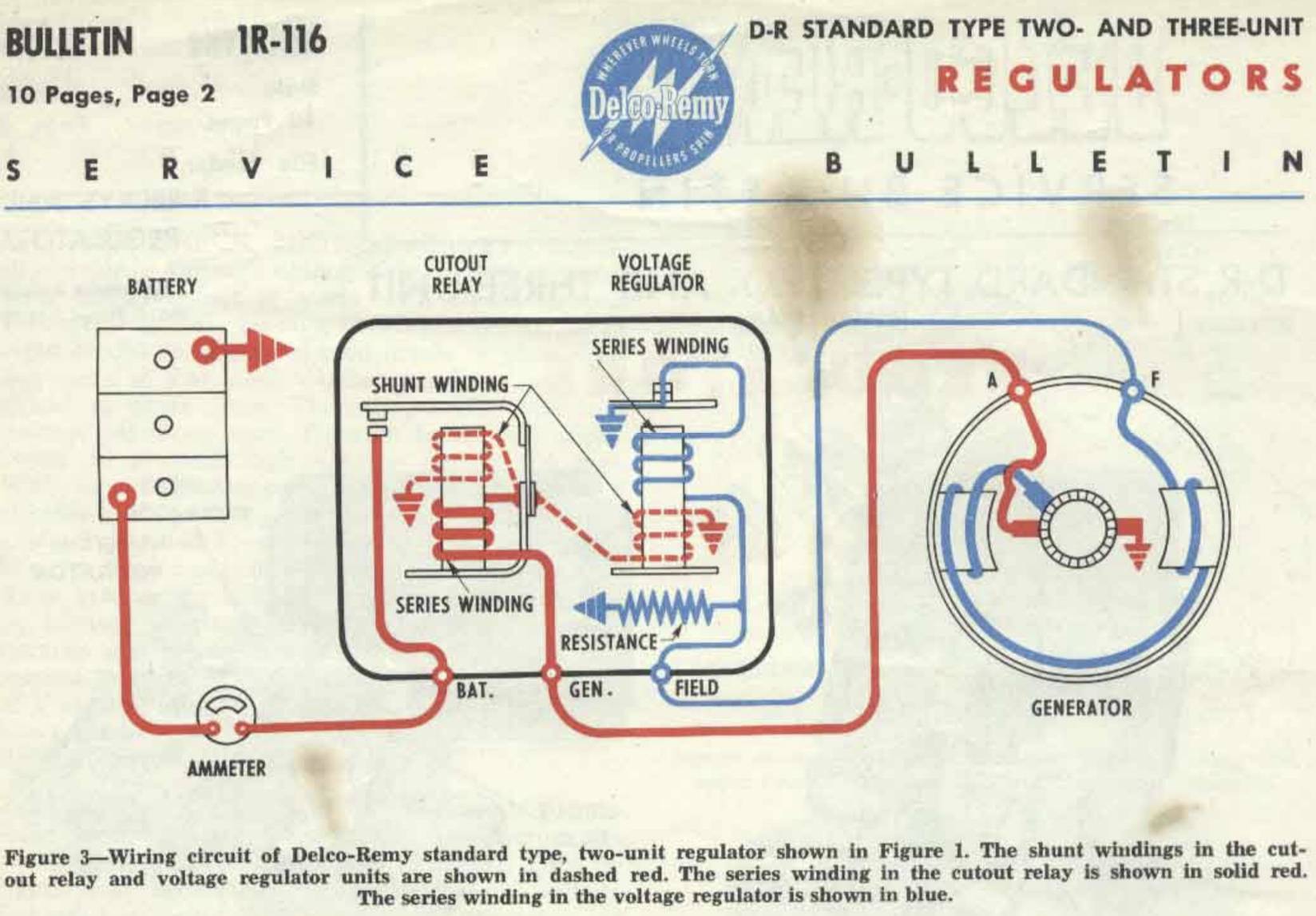 B503D5D1-CA9E-48F2-A809-CE15DEC91FDA.jpeg (88.80 KB) B503D5D1-CA9E-48F2-A809-CE15DEC91FDA.jpeg (88.80 KB)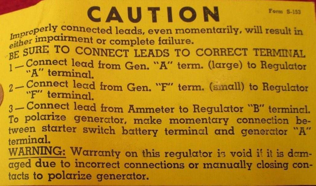
Posted on: 2022/10/30 15:39
|
|||
|
||||
|
Re: 1937 Battery Draw
|
||||
|---|---|---|---|---|
|
Home away from home
|
Hi, but no, I could not find anything stamped on the terminals telling me which is which. I'l try the ohmmeter process and see if I can determine which one goes where. The bat terminal is self evident to me now. It's just the other two I need to determine.
Thanks.
Posted on: 2022/10/30 16:55
|
|||
|
Roger Howe
Whitewright, TX 1937 120C Touring Sedan |
||||
|
||||
|
Re: 1937 Battery Draw
|
||||
|---|---|---|---|---|
|
Home away from home
|
Thanks. Yes, I did perform the ohmmeter test according to your instructions and found that the FLD terminal is the one located on the same side as the BAT terminal. I'll hook everything back up and run a test.
I do appreciate the instruction and immense help. Thanks, again.
Posted on: 2022/10/30 17:04
|
|||
|
Roger Howe
Whitewright, TX 1937 120C Touring Sedan |
||||
|
||||
|
Re: 1937 Battery Draw
|
||||
|---|---|---|---|---|
|
Home away from home
|
Hello, again. It finally warmed up enough here for me to be able to get back on my '37 120. I have located the battery draw, but I am not getting any measurement on my ammeter while the engine is running. After looking at the voltage regulator while running, I do not see the solenoid closing to allow current to flow back to the battery. I would like to test the relay in the regulator to see if voltage from the generator would close it but from what I understand I am not to come directly off of the battery due to the high amperage which would burn out the regulator. I can some up with some 6V ideas, but wondered if any of you have done this before and if so, what was your solution? I was thinking of getting a regular 9V battery which does not have that much amperage to see if that would close the relay. If it does, then I'll take the generator into the shop to have them check it out.
Thanks for your help as usual.
Posted on: 2023/1/1 16:22
|
|||
|
Roger Howe
Whitewright, TX 1937 120C Touring Sedan |
||||
|
||||


