|
Re: 1947 Super Clipper ammeter
|
||||
|---|---|---|---|---|
|
Forum Ambassador

|
There is not much electrically to go wrong with the ammeter. It is located in series in wiring between generator and battery. Essentially a flat strip of metal connecting one post to the other and shaped or configured to make sort of a loop. Current flowing thru that strip & loop makes it slightly magnetic which works on a piece of metal suspended near or inside the loop & attached to the needle. More current = stronger magnetism and the needle moves proportionally--whichever direction the current flows either from gen to battery or in reverse determines charge or discharge direction.
If something happened to the regulator and the charge rate was far above the design limit of the ammeter, some damage could have been done and ammeter could have became permanently magnetized or overheated. If that were the case, I would think you would have noticed some other symptoms such as very hot components or smoke from generator or regulator. Conversely, if the regulator cutout points stuck, battery would short thru generator with the same symptoms but on the discharge side. Old age or excess heat could have caused the phenolic support to have deformed or the ceramic supports could have broken --anything moving out of position so the needle is binding or not free to move smoothly anymore. Dried out and dirt could also be an issue. To test, I think about the only way is to have the charging system checked to make sure that is OK. If so, then substitution with a good but temporary aftermarket ammeter would tell the tale. Here is a picture of a slightly different 41 ammeter and the 47 both showing the phenolic support plate plus a diagram of the charging system showing how the ammeter wires in. Attach file:  (28.67 KB) (28.67 KB)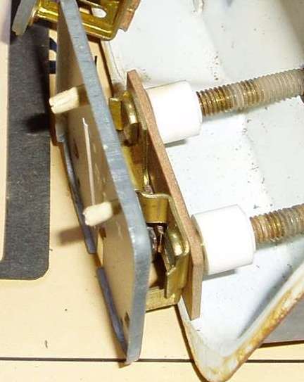 (24.94 KB) (24.94 KB)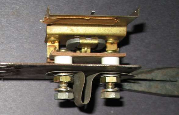 (55.55 KB) (55.55 KB)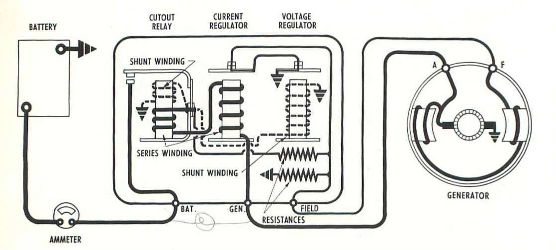
Posted on: 2011/10/4 18:10
|
|||
|
Howard
|
||||
|
||||
|
Re: 1947 Super Clipper ammeter
|
||||
|---|---|---|---|---|
|
Home away from home

|
1. Thks for the pic-better than the schematic. The cutout relay-the contact in series with the ammeter-possible it is open?
2. to test the ammeter-put a after market one in place of the one in the car? In other words connect it between the B terminal on the voltage relay and the neg battery terminal? thks for the reply David
Posted on: 2011/10/4 18:48
|
|||
|
||||
|
Re: 1947 Super Clipper ammeter
|
||||
|---|---|---|---|---|
|
Forum Ambassador
|
The regulator does need service at times. The contacts do take a considerable beating. Usually when cut out contacts fail, they weld shut.
The cut out relay is normally open. Residual magnetism in the generator is enough to start a slight voltage being generated as soon as it starts turning. When that voltage reaches a certain point, the cut out relay will pull in and connect the generator to the battery. Normal output and regulation can then start happening. Unless the engine slows way down at idle to drop voltage below the threshold, cutout will stay closed and connected pretty much until the engine is stopped. At normal speed and operation, the other two contacts will rapidly open and close to regulate voltage and current. To substitute, you could put a test ammeter in series with the original. Disconnect the wire at the BAT terminal on regulator & connect it to the temporary ammeter. Connect the other ammeter terminal back to the BAT terminal. You may have to experiment & reverse temp ammeter wires to get the orientation right so it would read correctly. Then just a matter of comparing the two.
Posted on: 2011/10/4 19:06
|
|||
|
Howard
|
||||
|
||||
|
Re: 1947 Super Clipper ammeter
|
||||
|---|---|---|---|---|
|
Home away from home
|
Howard thks-what is the "normal" amps in the circuit?
Posted on: 2011/10/5 8:41
|
|||
|
||||
|
Re: 1947 Super Clipper ammeter
|
||||
|---|---|---|---|---|
|
Forum Ambassador
|
"Normal" depends on what is operating. Lights, radio, OD, etc all pull current so it varies depending on what is turned on and condition of battery.
The Packard settings for maximum output of the Auto-Lite setup is 35 amps at 7.4v. Never measured it but I would guess that a charged battery with nothing on except engine & gauges should be pulling around 3 amps. After the generator had recharged the battery from the draw of the starting motor, then just a slight needle indication to the charge side would be on the ammeter.
Posted on: 2011/10/5 9:30
|
|||
|
Howard
|
||||
|
||||
|
Re: 1947 Super Clipper ammeter
|
||||
|---|---|---|---|---|
|
Home away from home
|
Well-put an ammeter in series with the battery and it appears the charging system is working. Increasing the speed of the motor-resulted in 6-10A. Idling slight discharge. I also tapped on the ammeter gage in the car and now it reads a sharp discharge with no flucation. I am going to leave it as is for a while and see what happens. I am not excited about getting under the dash.
Posted on: 2011/10/21 15:18
|
|||
|
||||
|
Re: 1947 Super Clipper ammeter
|
||||
|---|---|---|---|---|
|
Forum Ambassador
|
Don't blame you for not wanting to tackle removal. The pair come out together and there is some twisting and careful moving & sliding to get the mounted assembly out of the cluster without damage. Hard to say what is going on but unfortunately no way to tell without pulling them out.
Posted on: 2011/10/21 16:08
|
|||
|
Howard
|
||||
|
||||
|
Re: 1947 Super Clipper ammeter
|
||||
|---|---|---|---|---|
|
Home away from home
|
Another thought-could the problem be the indicator loose on the spindle?
Posted on: 2011/10/24 12:11
|
|||
|
||||
|
Re: 1947 Super Clipper ammeter
|
||||
|---|---|---|---|---|
|
Forum Ambassador
|
Anything is possible. In these photos you can see the needle is fairly well supported but perhaps one of the plates sandwiching the needle has loosened.
Some other possibilities although all are just guesses without examination: The tiny needle or point at a shaft end has broken or become gummed up where it enters it's support bearing. A fleck of paint loosened or lint or dirt somehow wound up inside and is causing a problem. In the photos I marked the vulnerable spot and then moved the needle. You can see the iron vane attached to the needle is suspended only about a hair's width above the current plate--each side the same. It's hard to tell, but there may be a tiny hair like centering spring hidden but mostly all is done essentially by balance. If there is a spring, it might have broken but at the least, anything that manages to lodge in that space or spring area will prevent free movement. The fiberboard or the ceramic supports the current plate is attached to has warped or broken and has thrown the front and back bearings out of alignment. Somehow the movement has become magnetized. Attach file: (19.62 KB)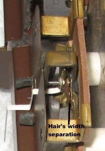 (29.40 KB) (29.40 KB)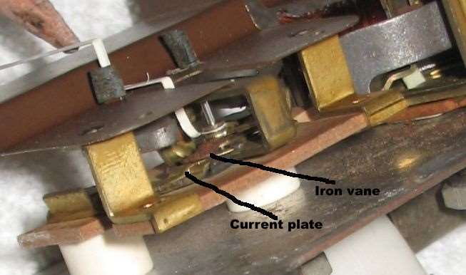
Posted on: 2011/10/24 13:03
|
|||
|
Howard
|
||||
|
||||


