|
Re: 1940 Turn Signal Wiring Diagram
|
||||
|---|---|---|---|---|
|
Forum Ambassador
|
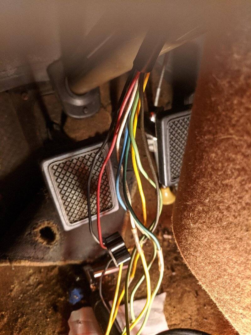
If you can find a brand name for the aftermarket turn signal setup you might be able to find a diagram by doing a Google search. If that particular switch was used heavily or sold by another car brand you might find something via one of their clubs or websites.
There were so many aftermarket turn signal setups available at places like Western Auto, Sears, Wards, JC Whitney and multitudes of independent parts stores and even corner gas stations thruout the 50s, to be different from another brand I doubt many of them used the same exact wire color schemes or even diagrams.
Posted on: 2021/10/3 13:56
|
|||
|
Howard
|
||||
|
||||
|
Re: 1940 Turn Signal Wiring Diagram
|
||||
|---|---|---|---|---|
|
Home away from home
|
As Howard suggested, Packard had no turn signals in 1940 so anything found on the cars was aftermarket. The main clue is the vinyl-covered wires as they were still cloth-covered until 1954 so the one in your car was a much later addition.
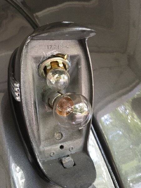
Fortunately adding turn signals was fairly easy as the fender lights were already wired with dual-element bulbs as were, of course, the taillights.
Posted on: 2021/10/3 14:03
|
|||
|
All generalities are false.
Once I thought I was wrong but I was mistaken. Don Pierson Packard / IMPERIAL page CA DMV Licensed Vehicle VIN Verification 1951 Henney-Packard 3-Door Long Wheelbase Air Force Ambulance The 1951 Henney-Packard is For Sale! 1954 Packard Patrician 1954 Packard Patrician Parts Car 1956 Clipper Custom Sedan |
||||
|
||||
|
Re: 1940 Turn Signal Wiring Diagram
|
||||
|---|---|---|---|---|
|
Home away from home
|
Gar;
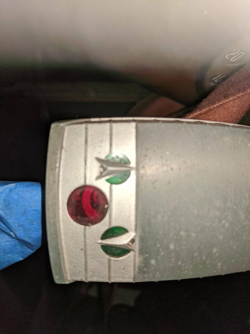
Because the pilot lamp is mounted inside the flasher housing, you should have 7 wires there. They are: 1. Stop light power input 2. Flasher power input In the photo looks like either the Red or Black wires 3. Flasher pilot lamp input In the photo looks like either the Red or Black wires 4. Right front lamp output 5. Left front lamp output 6. Right rear lamp output 7. Left rear lamp output The remaining brown wire in the 3 prong flasher socket should be perhaps hot always, or hot with ignition key on. Assuming you find power at the brown prong I would jumper power to the black prong. Stick a fuse in the jumper just in-case. If the indicating lamps turn ON then the black wire is the pilot lamp input, however if the lamps do not come on then place the turn signal switch into a ‘turning’ position and retry jumping brown to black. Assuming the lamps are good then one of the lamps should light, and you just confirmed the black wire is the pilot input. If this fails then you will have to repeat the process with the red wire, but I’m expecting the black to be the pilot and the red the load side of the flasher, that is, the flasher power input into the flasher switch. The next step is to find the brake light circuit. One of the wires should be hot only when the brakes are applied. You can trace the circuit from the brake light switch to the turn signal switch. Since wire 1 & 6, and 1 & 7 are common finding the brake light input power wire is best done by tracing the wire itself. The only wires left are going to the 4 corners of the car. One at a time we want to apply power and confirm which light is ON. Did I mention you’re writing all of this down, because once you’ve identified all 7 wires that’s your homemade wiring diagram. See thread ‘1956 Clipper Turn Signal’ posting #6. The attached diagram is for the Packard turn signal switch (it should be electrically identical to yours), but because the pilot lamps are dash mounted the Packard switch is a 6 wire design. dp
Posted on: 2021/10/3 17:36
|
|||
|
||||
|
Re: 1940 Turn Signal Wiring Diagram
|
||||
|---|---|---|---|---|
|
Home away from home
|
I forgot to add a sentence about front parking lights . . . if the car never had turn signals from the factory the front lights are not likely dual filament, therefore they need to be managed much like the stop lights. That is the turn signal shares a single filament with another function. Gar your wire count might be as high as 8 to cover the front bulbs. If we call the parking input power as circuit 8, then 8 & 4, and 8 & 5 will be common with the signal switch centered. With the switch in the right turn position then 2 & 4 are common, and 8 & 5 remain common.
Posted on: 2021/10/3 19:03
|
|||
|
||||
|
Re: 1940 Turn Signal Wiring Diagram
|
||||
|---|---|---|---|---|
|
Forum Ambassador
|
I think I count 7 wires from the switch so doing a search for 7 wire turn signal diagram brings up quite a few possibilities. You might compare a few of them to what you have in the way the flasher socket wires in and see if one looks appropriate.duckduckgo.com/?q=wiring+diagram+for+7+wire+turn+signal+switch&t=osx&iax=images&ia=images If none of them work then I think it will be back to finding a brand name or maybe even opening up the unit to try and identify the wire connections to the switch and match the colors.
Posted on: 2021/10/3 19:23
|
|||
|
Howard
|
||||
|
||||
|
Re: 1940 Turn Signal Wiring Diagram
|
||||
|---|---|---|---|---|
|
Home away from home

|
On a ‘40 the parking light are dual filament, so just attach to the second filament. For the taillight, you have to add a second, signal-dedicated socket.
Posted on: 2021/10/13 16:34
|
|||
|
||||
|
Re: 1940 Turn Signal Wiring Diagram
|
||||
|---|---|---|---|---|
|
Home away from home
|
Quote:
On a ‘40 the parking light are dual filament, so just attach to the second filament. For the taillight, you have to add a second, signal-dedicated socket. Adding a second socket is not necessary but you do have to add a separate wire so that the left and right brake lights each have their own. Once done, the switch connects through the brake light switch so when you press the pedal, both will illuminate as usual but when the signal is on, one will get its power through the flasher.
Posted on: 2021/10/13 18:31
|
|||
|
All generalities are false.
Once I thought I was wrong but I was mistaken. Don Pierson Packard / IMPERIAL page CA DMV Licensed Vehicle VIN Verification 1951 Henney-Packard 3-Door Long Wheelbase Air Force Ambulance The 1951 Henney-Packard is For Sale! 1954 Packard Patrician 1954 Packard Patrician Parts Car 1956 Clipper Custom Sedan |
||||
|
||||
|
Re: 1940 Turn Signal Wiring Diagram
|
||||
|---|---|---|---|---|
|
Home away from home
|
My rear and front lights have two pins in one socket. Running light and stop/turn light. So I should be good there.
Issue is trying to identify the correct wires with the turn signal, to work correctly out of the my 8 wire selection. Only wires I have successfully identified is the brake light wire and ground. May take it apart to do a deeper dive...
Posted on: 2021/10/14 8:26
|
|||
|
||||
|
Re: 1940 Turn Signal Wiring Diagram
|
||||
|---|---|---|---|---|
|
Home away from home
|
I disassembled the turn signal switch and was able to determine the feed (white wire),the brake light (black wire) and the emerg flasher (red wire).
Drk Grn & Blu are the left turn signal Yel & Brn are the right turn signal I appreciate all of the help.
Posted on: 2021/10/14 19:11
|
|||
|
||||

 IMG_20211003_132222.jpg (118.64 KB)
 87996698-60A0-4E4C-8D89-DA863FBF206D.jpeg (129.09 KB)