|
Re: BigKev's 1954 Packard Clipper Deluxe Sedan
|
||||
|---|---|---|---|---|
|
Webmaster

|
What range do you think the Resisters should be in? Also what type of Resistor would be the best?
Posted on: 2010/9/17 15:58
|
|||
|
-BigKev
1954 Packard Clipper Deluxe Touring Sedan -> Registry | Project Blog 1937 Packard 115-C Convertible Coupe -> Registry | Project Blog |
||||
|
||||
|
Re: BigKev's 1954 Packard Clipper Deluxe Sedan
|
||||
|---|---|---|---|---|
|
Webmaster
|
Howard,
Take a look at this regulated power supply schematic in this article. Looks simple enough to build. Only question I have, would there be any constant draw from the circuit itself even when the clock isn't pulsing. I think he built this to run 6v switched items like a radio, gauges, etc. http://www.public.iastate.edu/~lhealey/vespa/regulator/ For what it's worth, I wonder how long 3 AA batteries would power the clock?! lol
Posted on: 2010/9/17 16:30
|
|||
|
-BigKev
1954 Packard Clipper Deluxe Touring Sedan -> Registry | Project Blog 1937 Packard 115-C Convertible Coupe -> Registry | Project Blog |
||||
|
||||
|
Re: BigKev's 1954 Packard Clipper Deluxe Sedan
|
||||
|---|---|---|---|---|
|
Forum Ambassador

|
I think wire wound would be the best but to get in the proper watt range is important--so might have to take what you can get. Radio shack doesn't look like much help.
Without all the parameters it's a bit difficult to calculate. If we assume since it's fused for 3, then current is probably going to be 1 or 2--but that is a big guesstimate because it is not a pure resistive load. Doubt if you have anything fast enough to measure the current with and not sure my stuff is either but will see if I have a 6v clock this weekend and try. Resistance also might be a challenge as I would expect very low ohms for a small 6v coil. If you want to play around with some variables, here is a nifty sitehttp://www.the12volt.com/ohm/basics.asp and the calculator pagehttp://www.the12volt.com/ohm/ohmslawcalculators.asp Here is a page from Parts-Express with lots of choices.http://www.parts-express.com/wizards/searchResults.cfm?searchFilter=resistor%201%20w. EDIT: Google hijacks the parts express search if you want to look at them so just type in resistor 1 ohm. The circuit is similar to one we used all the time in another lifetime and is very reliable on a resistive load. It sounds as if he is running the original vibrator radio on it and if so, then it should certainly work on the clock although I think the vibrators are buffered a bit. At less than $10 and an hour or two, definitely worth a look.
Posted on: 2010/9/17 16:40
|
|||
|
||||
|
Re: BigKev's 1954 Packard Clipper Deluxe Sedan
|
||||
|---|---|---|---|---|
|
Webmaster
|
Radio Shack really just isn't what it used to be. They only had the LM7805 (5v) and LM7812 (12V) regulator ICs. So I will have to source a couple LM7806's online.
I did pick up a couple of 1 ohm, 10watt wire wound resistors. First I will piece together 4 AA batteries to build a 6v (1.5 x4) source, and then I can try to check what the clock is pulling as far as a load. Got the glove box light working. I had forgot to put a bulb in it...doh! I also figured out what the heck was going on with the cigar lighter. I was using an aftermarket socket that I bought when I first got the car as the cigar lighter was missing. The problem is that the way it is designed, the grounded outer shell of the Packard element shorts against the hot feed when pushed in. So I swapped the socket to a Packard one that I had picked up in a junk box of mixed parts I got at a swap meet, problem solved. I did have to bend out the little tangs on the side of the element as the first time it heated up and popped out, it popped all the way out of the socket and rolled under the seat....while hot! I let the car warm up until the temp on the head read 180f on my IR thermo, as which point the temp gauge on the dash was dead center in the middle. So looks like that checked out. I also took my gas can and got exactly 5 gals of fuel for the gas station, and put it in the Packard. At which point the fuel gauge read 1/4 tank. So I think that is about right. I guess the tank was a bit on the empty side, or there was only enough fuel to be in the reserve portion of the tank. Before I added the 5 gals, the gauge was reading right on the empty arrow mark. Check the horns on the car, they worked for about 5 seconds and then stopped. I am using the horn relay that built into the new fuse box. I thinking that the fuse box relay/fuse is not rated for what those old 6v horns pull. So I may need to go back to the beefier fender mounted relay for those horns. I also need to pull apart the dome light switch that is on the Passenger B-Piller (rear passenger switch) as it is not working. Probably the contacts are dirty as you can hardly move the switch by hand. All part of the fun of bringing a car that has sat abandoned out in the elements for 20 years back online.
Posted on: 2010/9/17 22:28
|
|||
|
-BigKev
1954 Packard Clipper Deluxe Touring Sedan -> Registry | Project Blog 1937 Packard 115-C Convertible Coupe -> Registry | Project Blog |
||||
|
||||
|
Re: BigKev's 1954 Packard Clipper Deluxe Sedan
|
||||
|---|---|---|---|---|
|
Webmaster
|
More progress this morning. I got the clock working and running. I started by fixing the two clocks on the the two spare dash clusters I have. They both had the same issue, fried contacts and they needed lubrication. I wired the two 1 ohm, 10 watt wire-wound resistors together in series and then shrink wrapped them together to form a little brick, and attached one lead with a ring terminal to the post on the back of the clock and the other lead to my 13.8v power source. When checked with an amp meter, the clock pulls about 2.5 amps with the contact points stuck together. So that is the worst case scenario. Plus I am not worries about the resistors getting hot as the winding load is only a fraction of a second every couple of minutes.
Before trying to get the electrical winder on the clock working, with I wanted to get the actual clock mechanism working itself. You can manual wind it moving counter weight lever on with either side. Once wound, neither clock started ticking. So the first clock I saturated all the gear work with PB Blaster, and then moved the time adjusted to get gears moving a bit so the lubricant could work in. I set that clock down and didn't the same think with my second clock. The second clock started to tick with the first shot of PB. The first clock I needed to run manual start the little pendulum gear a couple of times, and then it started ticking on it own. I guess it just needed longer for the PB to work in. I blotted up an of the extra PB-Blaster from both clocks, and let them run, rewinding them as needed. After about 15 minutes, with them both running and keeping time, I figured the clock mechanisms were sound and working. So I moved onto the electrical. Both only needed the contact points dressed. This was done with a thin metal file (point file). Then I hooked up the resistor block to the clock, and bingo, it wound the clock, and I let it go for about 30 mins. Each time it wound the clock without an issue. The winding happens in a split second, it it pulls anywhere between 30-70 milliamps during that operation according to my multimeter. But it could pull more, and my multimeter may not be able to sample that fast. When the clocks are not being wound, they pull no current at all. So feeling good about getting the two spare clocks running, I moved on to the clock that is actually in my car. It was by far the worst. Not sure if it was because of the amount of moisture it was exposed to over the years or what, but it took a couple rounds of PB to get the mechanism running once wound. The points on this one were also stuck together. I hooked up resistor and electrical to it, and nothing, no amp load registered. Upon further inspection there are two thin metal tabs that are soldered together mid run right above the coil and under the points. I think this is a fail safe that is part of the clock in the event the points short and the fuse doesn't blow. On my clock the soldered melted and the tabs separated. If you remember when I took the cluster out of the car, someone had used foil bypass a blown fuse in the clock. Also when I found the car, it has a 12v battery in it. So I think the points stuck together, and with the fuse bypassed, it simply heated up the coil in the clock until the solder failed. I re-soldered the tabs back together, and bingo, clock now works again. Then I reinstalled the clock back in the cluster, and the cluster back in the dash. Hooked the battery back up, there was an initial 50 milliamp spike as it wound, then zero load. Then about 2-3 minutes later, another 50 milliamp spike as it wound again (rinse and repeat). It's now been ticking away in the dash for a couple of hours, and keeping good time. Attach file:  (93.56 KB) (93.56 KB)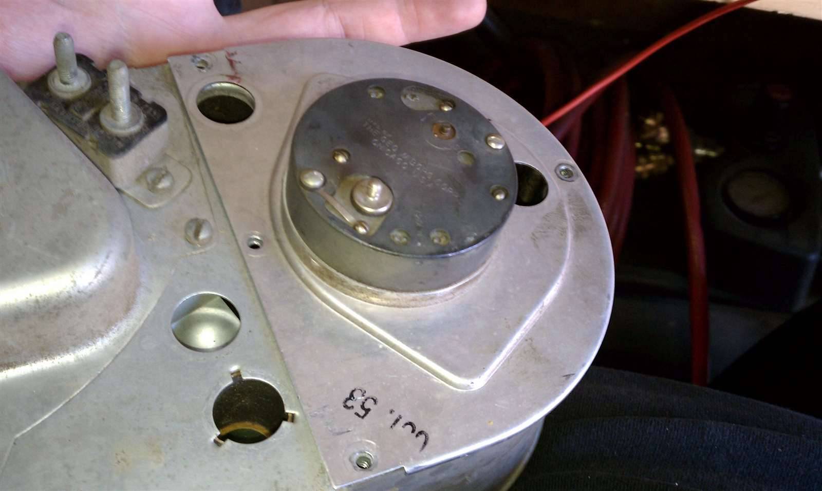 (107.69 KB) (107.69 KB)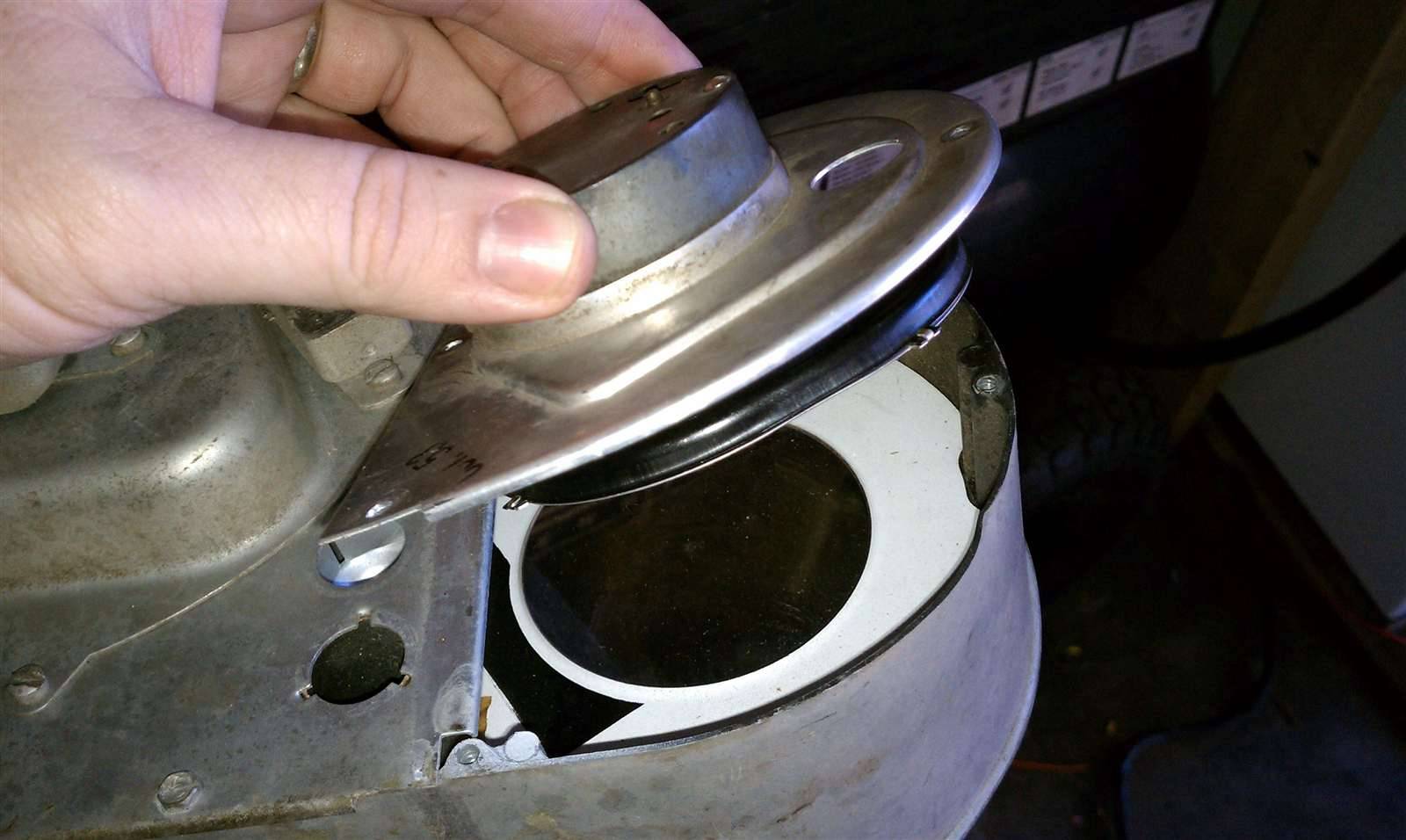 (138.07 KB) (138.07 KB)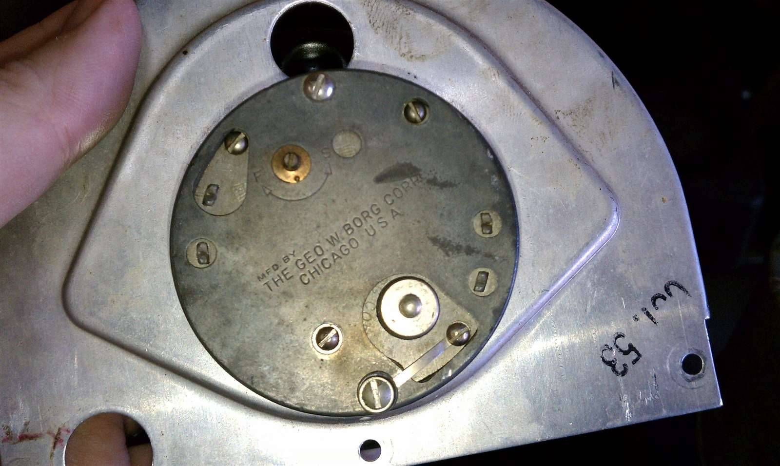 (126.40 KB) (126.40 KB)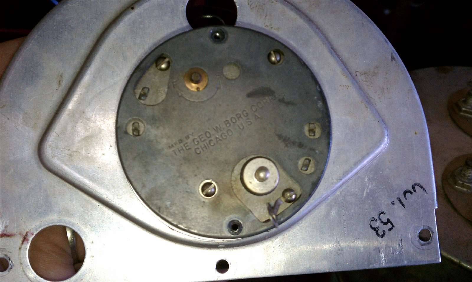 (84.68 KB) (84.68 KB) (103.16 KB) (103.16 KB) (132.51 KB) (132.51 KB) (128.16 KB) (128.16 KB)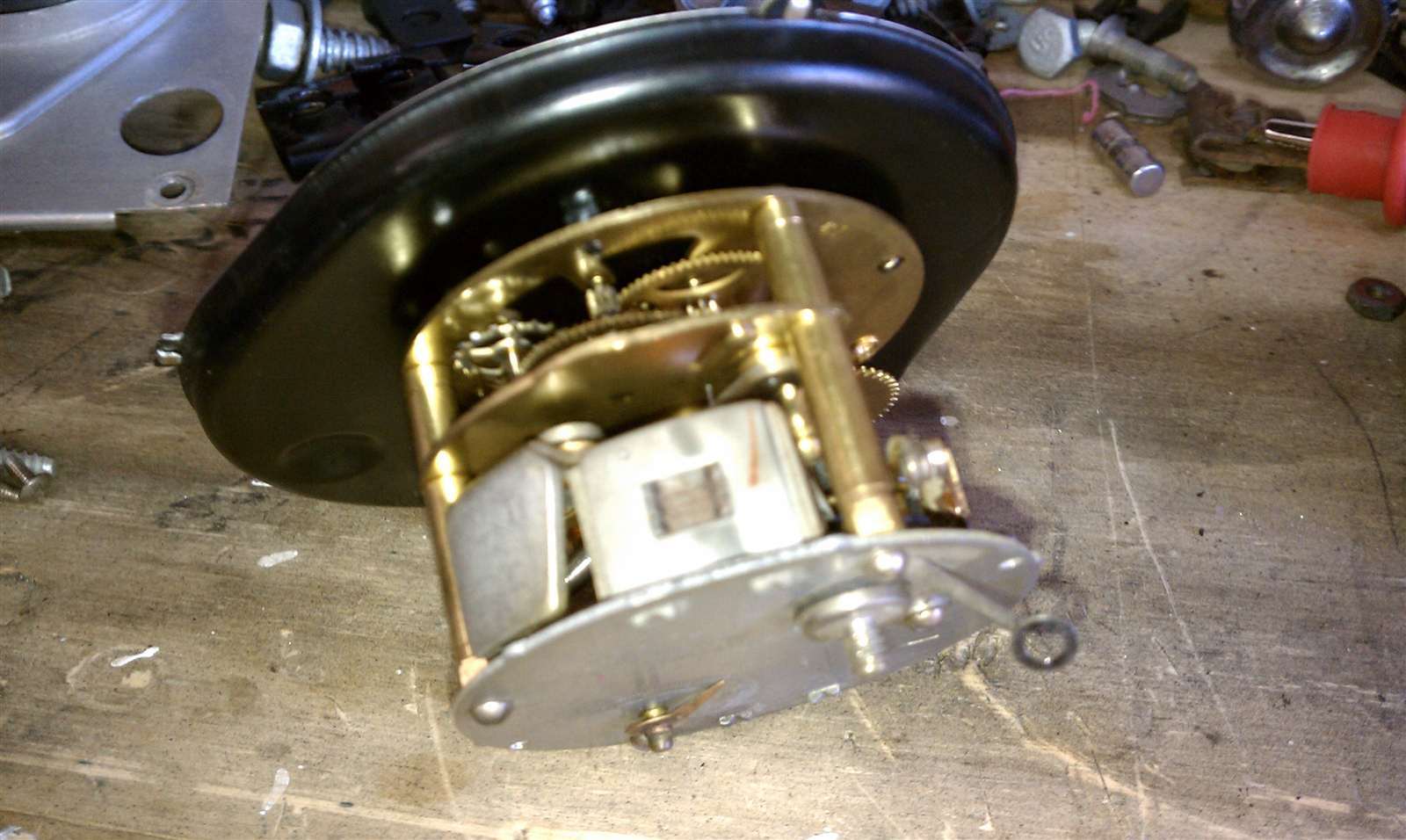 (106.71 KB) (106.71 KB)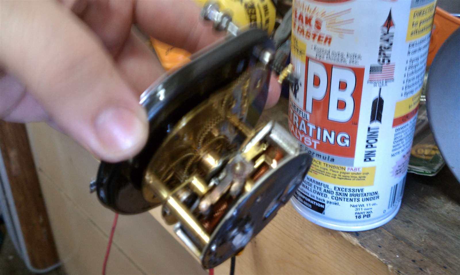 (94.81 KB) (94.81 KB)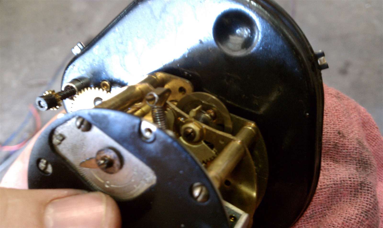 (111.73 KB) (111.73 KB) (148.14 KB) (148.14 KB)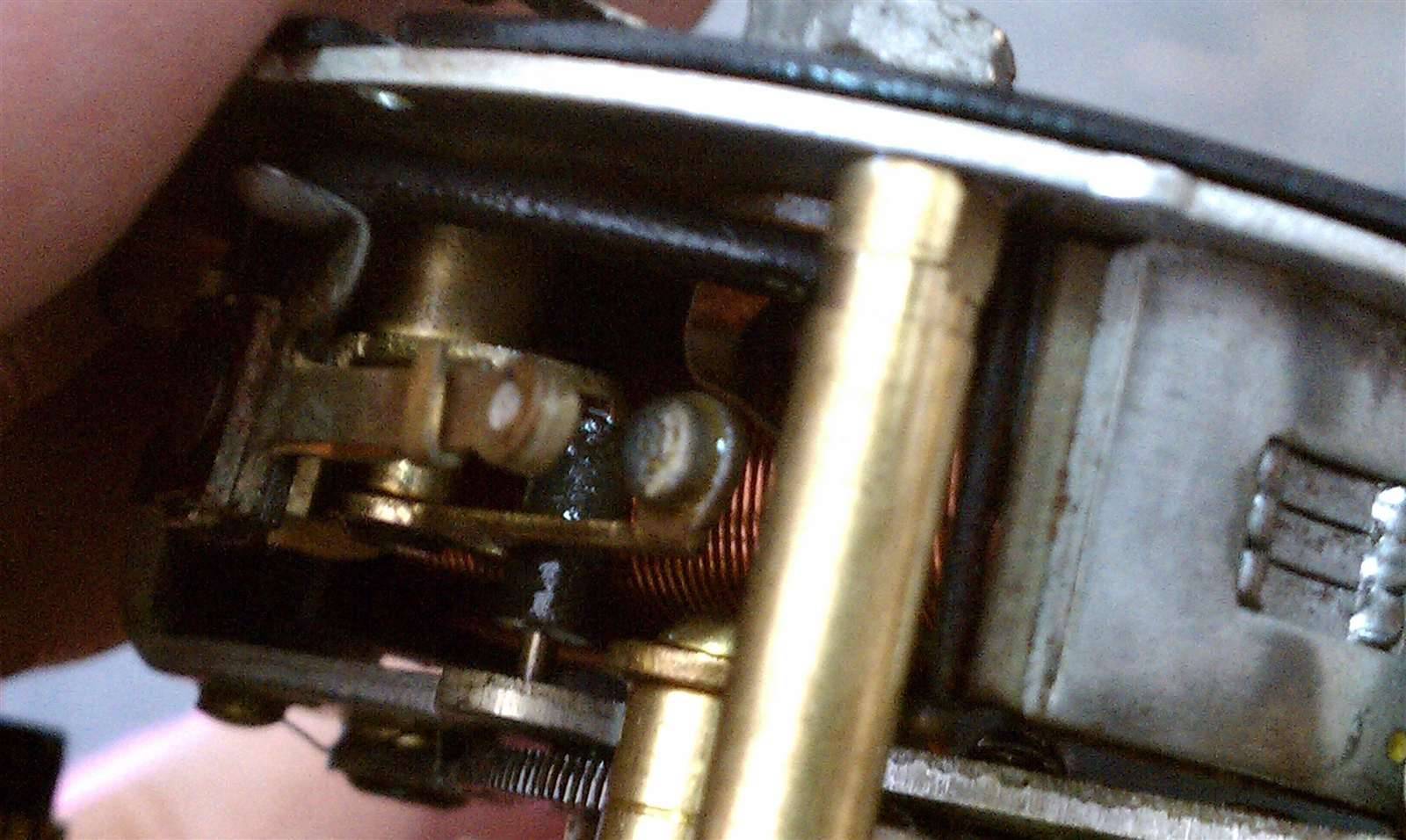 (131.02 KB) (131.02 KB)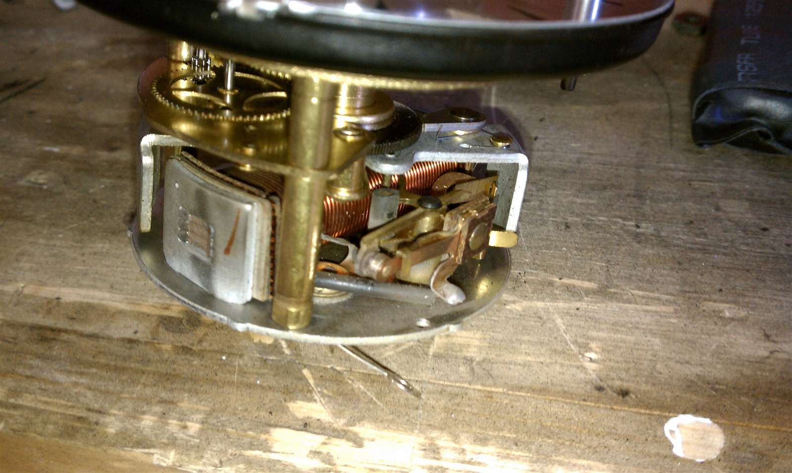 (118.23 KB) (118.23 KB)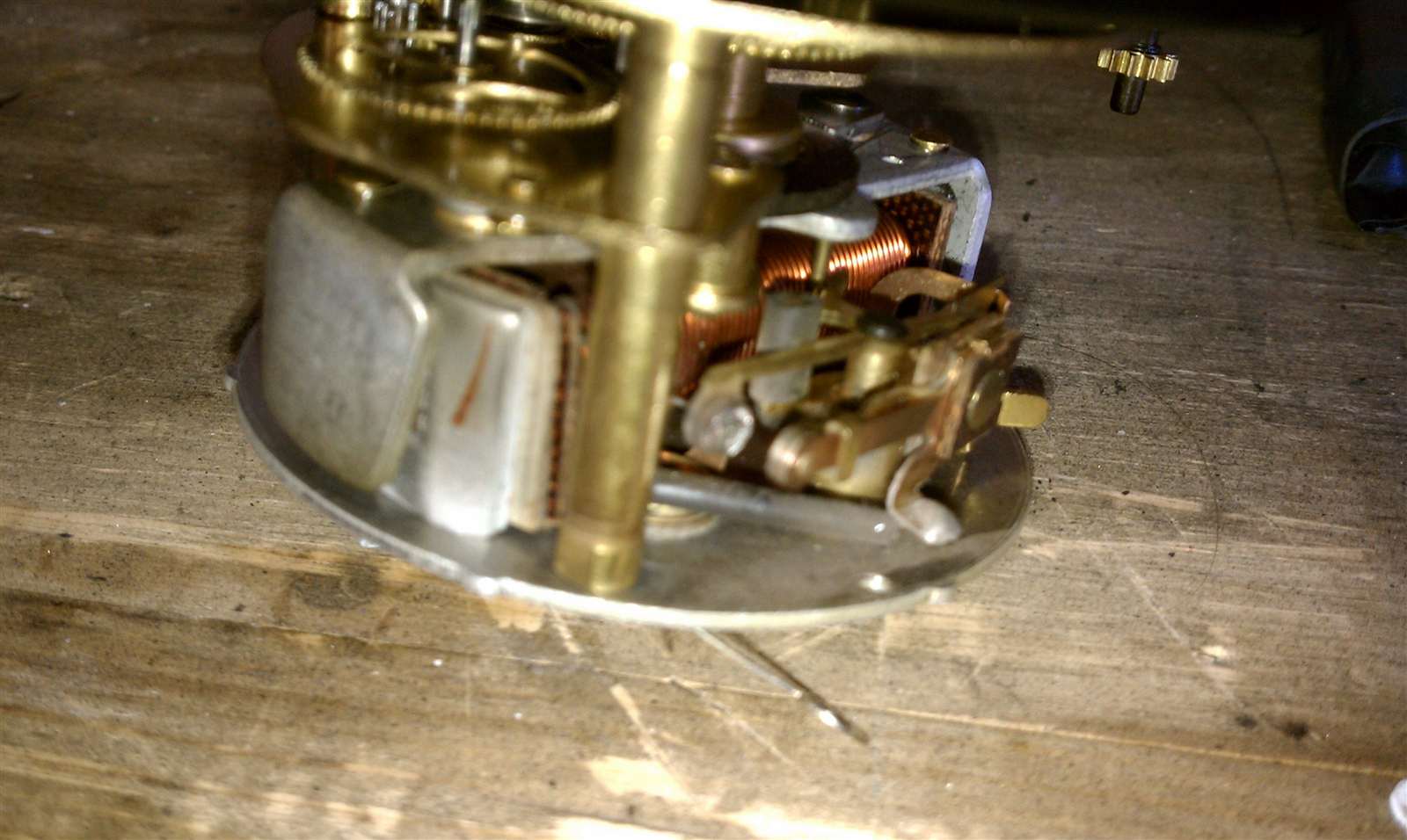 (110.20 KB) (110.20 KB)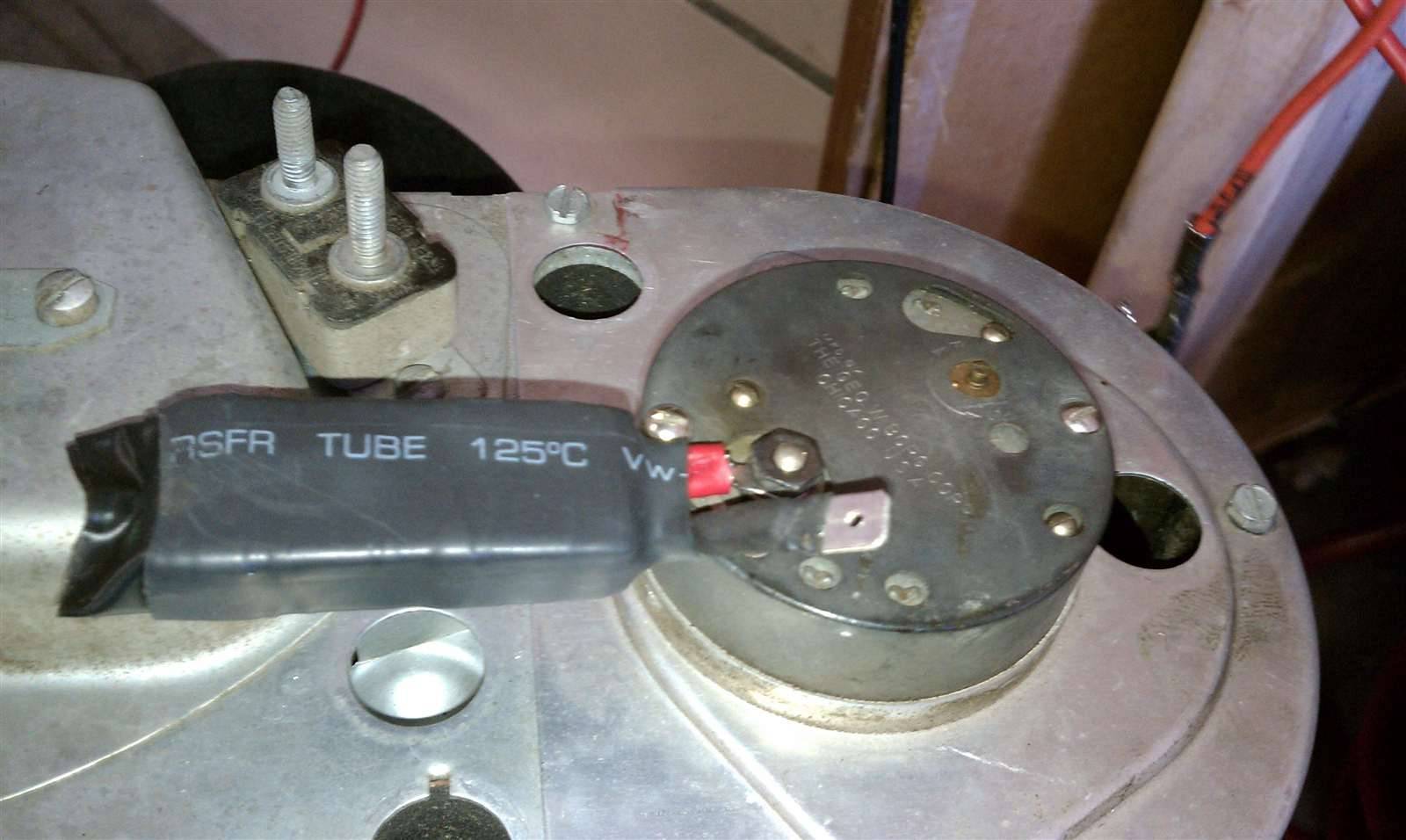
Posted on: 2010/9/18 17:17
|
|||
|
-BigKev
1954 Packard Clipper Deluxe Touring Sedan -> Registry | Project Blog 1937 Packard 115-C Convertible Coupe -> Registry | Project Blog |
||||
|
||||
|
Re: BigKev's 1954 Packard Clipper Deluxe Sedan
|
||||
|---|---|---|---|---|
|
Webmaster
|
Some additional progress today. Got the main portion of the front grille mounted and also painted and mounted the bumper filler panel. With the grille mounted I was able get the parking light wired up and mounted.
The grille on my car was smashed when I got it, so I picked up a driver quality one from Dan Yocum when I first got the car (many moons ago). But it never was mounted on the Clipper. It had two cracked parking light housings when I got it. This was a common problem with 53-54 grilles. I have replaced both housings. The one on the passenger side is really good, and the one of the drivers side is so thin that the copper layer is bleeding through. So I will either have to get it rechromed at some point or find a good driver quality one to replace it with. Still need to install all the under fender grille mounting bolts, and also install the bumper extensions and the '54 Deluxe/Super fender trim that mounts underneath the extension. Attach file: (154.77 KB)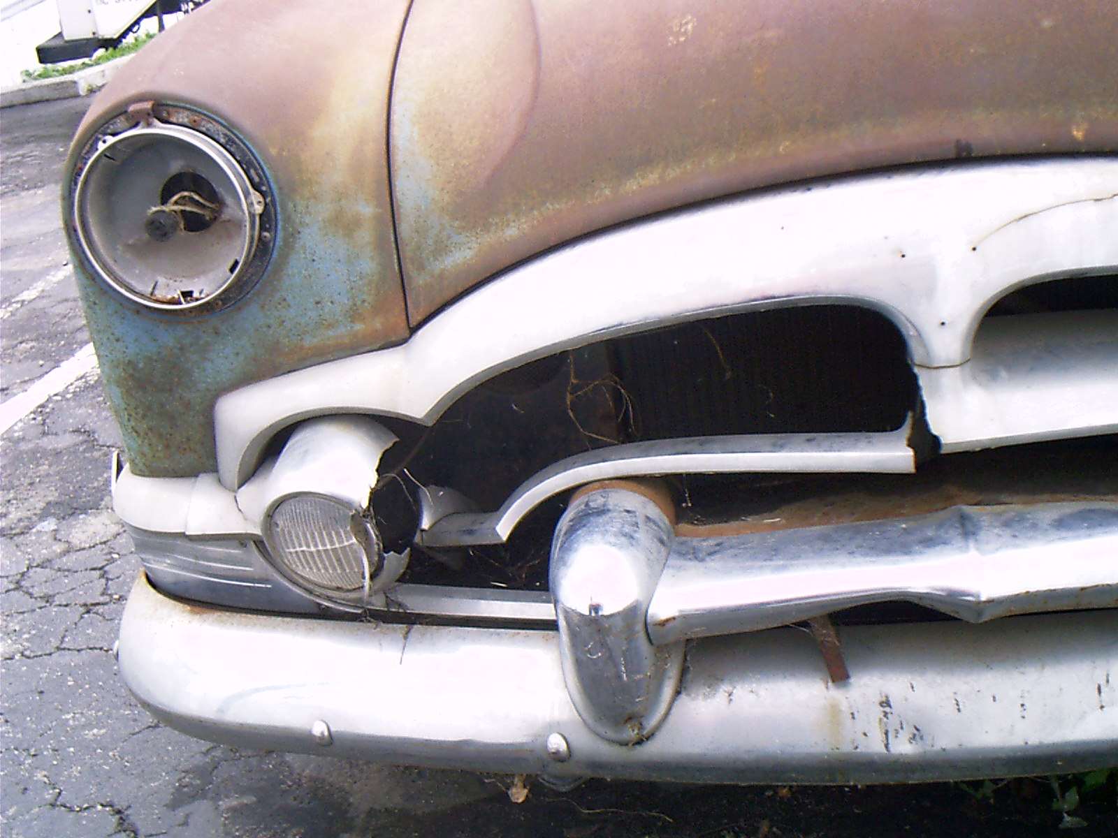 (154.90 KB) (154.90 KB)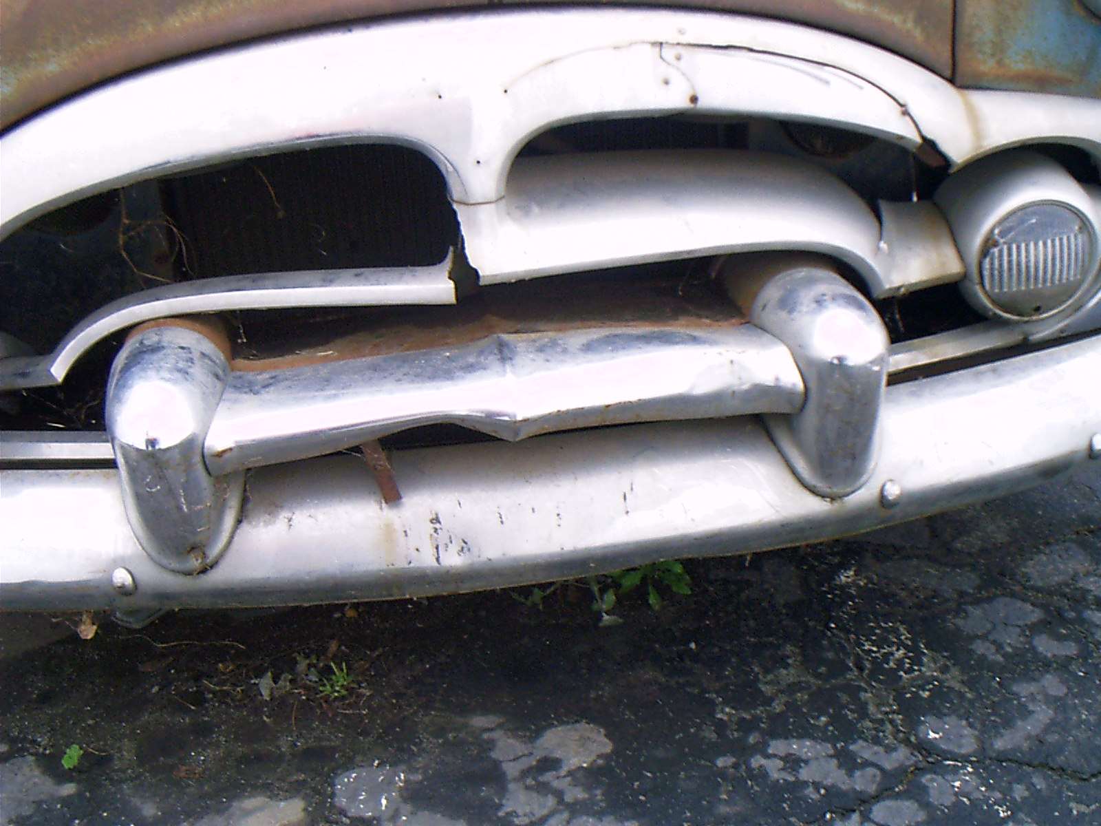 (187.06 KB) (187.06 KB)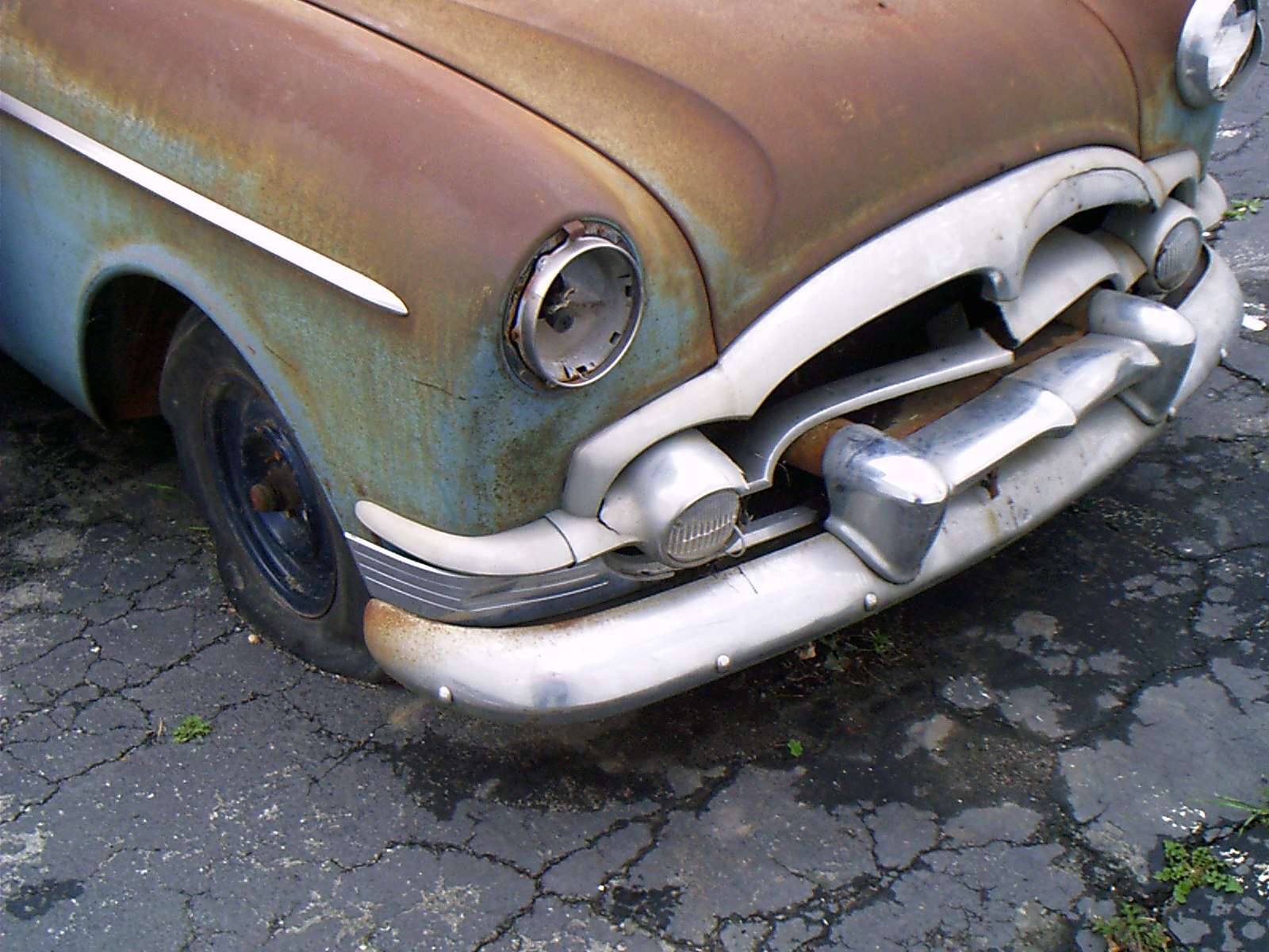 (117.17 KB) (117.17 KB) (124.15 KB) (124.15 KB)
Posted on: 2010/9/19 22:10
|
|||
|
-BigKev
1954 Packard Clipper Deluxe Touring Sedan -> Registry | Project Blog 1937 Packard 115-C Convertible Coupe -> Registry | Project Blog |
||||
|
||||

|
Re: BigKev's 1954 Packard Clipper Deluxe Sedan
|
||||
|---|---|---|---|---|
|
Forum Ambassador

|
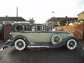
Like Hank, Cli55er, I believe the before and after pic's make great viewing. You can really see the progress made Kev.
Posted on: 2010/9/19 23:09
|
|||
|
Mal
/o[]o\ ====  Bowral, Southern Highlands of NSW, Australia "Out of chaos comes order" - Nietzsche. 1938 Eight Touring Sedan - SOLD 1941 One-Twenty Club Coupe - SOLD 1948 Super Eight Limo, chassis RHD - SOLD 1950 Eight Touring Sedan - SOLD What's this?  Put your Packard in the Packard Vehicle Registry! Here's how! Any questions - PM or email me at ozstatman@gmail.com |
||||
|
||||
|
Re: BigKev's 1954 Packard Clipper Deluxe Sedan
|
||||
|---|---|---|---|---|
|
Home away from home
|
Hi Kev,
I really like the way your car is progressing and found the blog on the clock repairs especially interesting. I admire the way you tackle any job that comes along. Keep up the good work as the light in the tunnel is getting much brighter now. Regards Terry P.S I have sent you a pm in regard to your picture posting
Posted on: 2010/9/20 2:24
|
|||
|
||||
|
Re: BigKev's 1954 Packard Clipper Deluxe Sedan
|
||||
|---|---|---|---|---|
|
Webmaster
|
Thanks guys, I appreciate the comments!
Terry, just checked my InBox...no PM was received. 
Posted on: 2010/9/20 12:30
|
|||
|
-BigKev
1954 Packard Clipper Deluxe Touring Sedan -> Registry | Project Blog 1937 Packard 115-C Convertible Coupe -> Registry | Project Blog |
||||
|
||||


