|
Re: 48-50 Bimetal Senders Retrofit Project
|
||||
|---|---|---|---|---|
|
Home away from home
|
Quote:
I appreciate it, though I'm not sure it would be needed. Since what I have in mind would be that someone can buy a generic sender with a linear response, and have that adapt as well as reasonable to the factory gauges. The other thing is that, as far as I am aware, the usual rheostat senders have a low resistance when full and high when low. But David's chart is the opposite. Edit: Actually seems like low ohm empty and high ohm full is the standard, at least for GM.
Posted on: 5/3 19:38
|
|||
|
'55 400. Needs aesthetic parts put back on, and electrical system sorted.
'55 Clipper Deluxe. Engine is stuck-ish. |
||||
|
||||
|
Re: 48-50 Bimetal Senders Retrofit Project
|
||||
|---|---|---|---|---|
|
Forum Ambassador

|
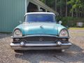
For completeness, here is what Motor's Manual, Fifteenth edition has to say about the operation of the Ford and King-Seeley temp, fuel, and oil gauges as used on 22-23 series. Packard used the single sender temp gauge implementation.
As an extra I kept the Stewart-Warner fuel gauge info visible. The fuel and oil gauges are magnetic type gauges and were used on 42-47 Clippers. In addition to the sender the magnetic gauge itself must also have a good ground to work. Fuel sender had an obsolete S-W range of l00 ohms empty and 0 ohms full. Suspect oil sender had the same ohm range but temp gauge on Clippers was the direct read mechanical pressure bulb style. Attach file:  22-23 K-S temp ga operation.jpg (570.16 KB) 22-23 K-S temp ga operation.jpg (570.16 KB)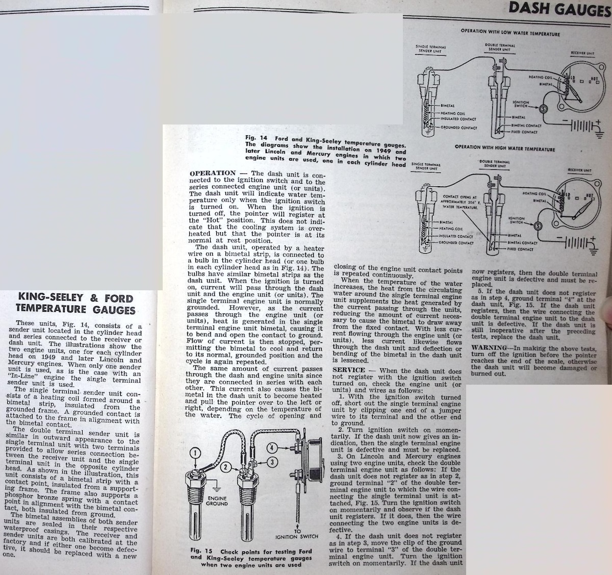 Fuel.jpg (825.35 KB) Fuel.jpg (825.35 KB)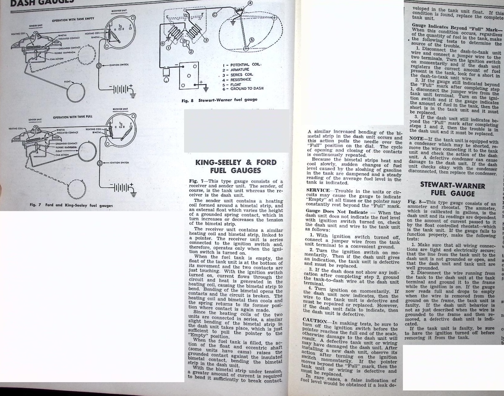 oil.jpg (685.01 KB) oil.jpg (685.01 KB)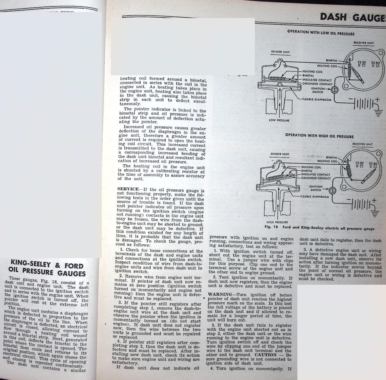
Posted on: 5/3 20:17
|
|||
|
Howard
|
||||
|
||||
|
Re: 48-50 Bimetal Senders Retrofit Project
|
||||
|---|---|---|---|---|
|
Home away from home
|
Thanks Howard. I'll read through those shortly.
I have a Chilton's (?) manual but idk if it goes back that far. From the service letter and DP's data it's clear that the water temp gauge indicates backwards compared to the other two, but with the same range. At least for the gauge, this can be easily accomplished by physically reversing the assembly inside it during the manufacture process. Therefore it may be assumed that the oil and gas gauges operate according to DP's data, just reversed. I.e. a high impedance at the sender gives a low gauge reading and vice versa. It should be noted that all 3 gauges on the later cars followed this same pattern of high impedance = low reading. Actually I'm not certain on the oil pressure gauge, so maybe Howard can confirm that. I think if there is a device that can trim both for an input threshold, and an output range, and can reverse the logic between input and output, it could be easily set up to make any sender work properly with any gauge. I'll have to see if I can come up with something. Of course, this would work not only for the 48-50, but the other obsolete types and also for all makes. Thr only assumption is that both scales are linear, so if I can make a decent "reverse exponential" device separate for 48-50 it may be best to do so.
Posted on: 5/3 21:55
|
|||
|
'55 400. Needs aesthetic parts put back on, and electrical system sorted.
'55 Clipper Deluxe. Engine is stuck-ish. |
||||
|
||||
|
Re: 48-50 Bimetal Senders Retrofit Project
|
||||
|---|---|---|---|---|
|
Webmaster

|
They make micro arduino boards that have various pins that can be used for input and output. They are cheap also, like $10. But with some code you can program them to accept certain ranges and then trigger output pins which can light up LEDs.
Only thing you would need is a step-down voltage I/C as most of those boards are 5v. I'd recommend a one that puts out stable voltage regardless of input voltage which can fluctuate in a car, as these micro controller boards are pretty voltage sensitive. But those ICs are fairly cheap as well and those boards are low amperage. That would be the most flexible option as then you can have different programs based on the sender OHM ranges, with the exact same hardware. But those output pins could also be used to produce a different outout range. So you could use one to translate from one type of sender to another.
Posted on: 5/4 8:21
|
|||
|
-BigKev
1954 Packard Clipper Deluxe Touring Sedan -> Registry | Project Blog 1937 Packard 115-C Convertible Coupe -> Registry | Project Blog |
||||
|
||||
|
Re: 48-50 Bimetal Senders Retrofit Project
|
||||
|---|---|---|---|---|
|
Home away from home
|
The float level on the Carpenter sender is adjustable and I can confirm that the bolt pattern is identical to the Packard one since I bought spare gaskets from them which fit perfectly.
Posted on: 5/4 8:49
|
|||
|
||||
|
Re: 48-50 Bimetal Senders Retrofit Project
|
||||
|---|---|---|---|---|
|
Home away from home
|
Quote:
That's true, and not a bad idea. I've used Ardunios many times in the past. And an Arduino Nano has the necessary ADC on it to process an input of variable resistance. The main drawbacks are that it can't be standalone. It needs: - power supply (6-15V to 5V) - precision voltage divider for the input - output driver, since the 20mA per pin of the Arduino is only about 1/25 of what's needed to drive the gauge reading. Also, while programming these is simple enough, it could be a benefit to sell something the user can just set up and trim themselves. Of course you can add some pots to the Arduino but at that point you may as well make a custom daughterboard. And then we should consider an enclosure for it... This really shouldn't be terribly hard with a few op amp circuits combined. Will have to play with it but have been under the weather today, so not been on my PC.
Posted on: 5/4 18:23
|
|||
|
'55 400. Needs aesthetic parts put back on, and electrical system sorted.
'55 Clipper Deluxe. Engine is stuck-ish. |
||||
|
||||
|
Re: 48-50 Bimetal Senders Retrofit Project
|
||||
|---|---|---|---|---|
|
Forum Ambassador
|
If you can do without a trim pot and shrink the board to a small enough size you could make something that would mount directly on the two input studs on back of the gauges. Power would then be readily available and with addition of a pigtail to a nearby screw to provide ground, would be self contained. The sender wire could be removed from the original gauge connection and placed on a new terminal on the board with the connection back to the gauge being also used as part of the mounting. Use an easily found and commonly available modern range resistance sender used on many aftermarket gauges such as the almost universal S-W range of 33-240 ohms.
I think you would need some kind of protection on the sender input as all the EMF noise or spikes in the car could easily be picked up by that long unshielded sender lead. If the components are CMOS might also need extra input protection for probable static generated by poor handling when connecting wiring, particularly if working with the sender at the gas tank. Here is the back of a 22-23 cluster that BDeB posted some time ago. Attach file: 22-23 cluster.jpg (206.16 KB)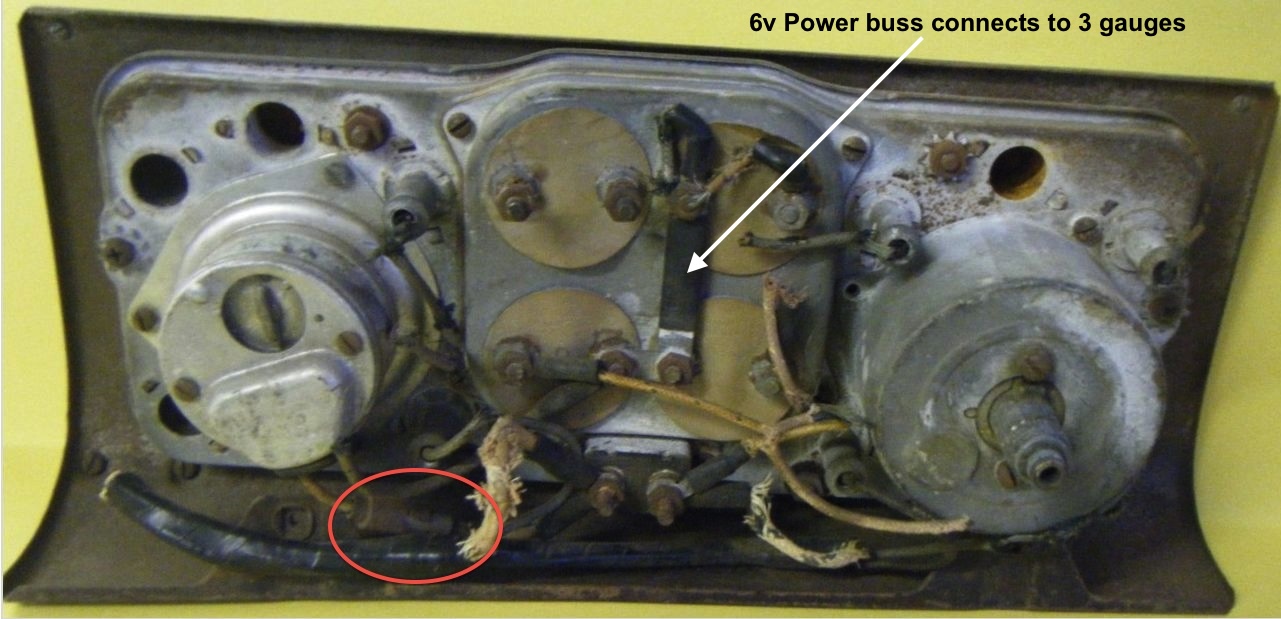
Posted on: 5/4 19:07
|
|||
|
Howard
|
||||
|
||||
|
Re: 48-50 Bimetal Senders Retrofit Project
|
||||
|---|---|---|---|---|
|
Home away from home
|
Thanks Howard. Yes, I'm going to add some basic EMF protection. Dang EMF's.
I've come up with something here that should work well. The sender is represented as a potentiometer on the right. It is connected to +6.3V (car ground) and the other side is the circuit input. The 10u gives ripple/noise protection on the order of 50ms. The 4.7k+4.7k and 1k, then also the 100k and 4.7k+10k pot, form a differential amplifier with the left op amp. This basically inverts the signal. The pot is to "zero out" the signal depending on the sender minimum resistance. The second op amp is a simple amplifier whose gain is controlled by the pot above it. To set up this device, all you have to do is: 1: Hold the sender at "empty" (lowest resistance). 2: Set the first pot so the gauge reads empty. 3: Hold the sender at "full" 4: Set the second pot so the gauge reads full. This works for a variety of gauges and senders, such as 0-100, 20-120, 30-330, etc. The values are pretty consistent over a varying input voltage; at least, not any more inconsistent than factory. This problem is naturally corrected on the later cars that have voltage regulators for the gauges. This one in particular gives a high output when for a high input (low resistance). [Type 1] 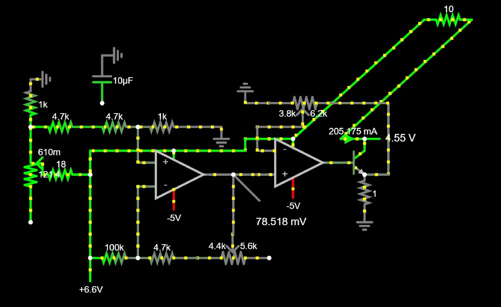 For systems where you need a low output for a high input (low resistance), there are some minor changes. [Type 2] Basically just to reverse the differential amplifier. Oh, and you must swap the words "empty" and "full" in the above instructions. 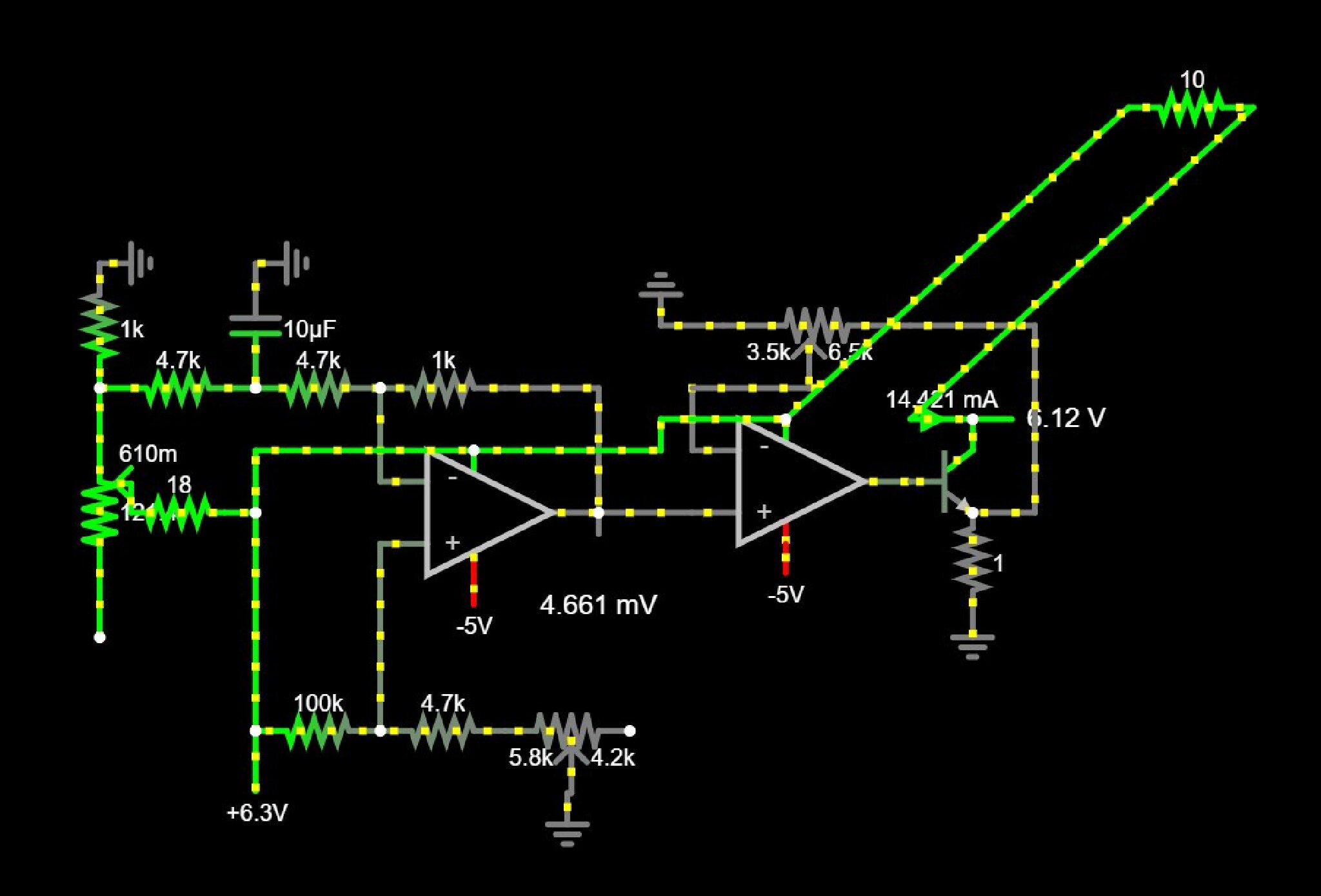 What I mean by high/low output and high/low reading is: for example, the 1955 fuel senders are 73 ohms empty and 10 ohms full. Obviously the fuel gauge will read low empty and high full. Likewise, since the current output of the sender is inversely proportional to the resistance, this means that a low sender output = a low gauge reading. So you need a "type 1" module. So let's say you use the Ford unit in your 48-50. If you have no sender connected to the gas gauge, it reads low. Likewise, an empty tank gives a high resistance from the Ford sender. So you need a "type 1" module. However, let's then say that you find a comparable water temp sender that has high resistance when cold, but low when warm. If you hooked this to the fuel gauge it would read "correctly" but if you hooked it to the water temp gauge it would read "backwards". So you would need a "type 2" module. Realistically I think I would package both a single "type 1" and "type 2" onto the same board since the individual component cost is so cheap, plus there needs to be additional power supply circuitry not shown so the overall cost difference would be negligible. Also, I've already found that with some minor tweaks you can use these on positive ground cars too.
Posted on: 5/5 13:35
|
|||
|
'55 400. Needs aesthetic parts put back on, and electrical system sorted.
'55 Clipper Deluxe. Engine is stuck-ish. |
||||
|
||||
|
Re: 48-50 Bimetal Senders Retrofit Project
|
||||
|---|---|---|---|---|
|
Home away from home
|
I did a second round of K-S instrument testing on my ’48.
The purpose of this round of testing was to investigate whether the instrument panel gauges are essentially the same electrically. Beginning with the coolant temperature gauge a potentiometer was used in lieu of the sending unit. This potentiometer was adjusted to deflect the needle to mid-span. This test was repeated several times resulting in 30.8 ohm, 0.142 amp, and 36.1 ohm, 0.126 amp data sets. The second potentiometer setting was then applied to the oil pressure gauge which resulted in a needle deflection to approximately 45% of full scale (just under 40 psi). The resistance was then reduced until the current was 0.146 amp, and the needle indicated mid-scale (40 psi exactly). Results of the first test of the coolant temperature gauge indicated a heightened degree of non-linearity (needle position versus current) at mid-span. Seems that some type of test protocol will need to be created to explore whether hysteresis is part of resistance/needle position repeatability. For both gauges the potentiometer was adjusted to produce equal voltage drop between the panel instrument and the simulated sending unit. The coolant temperature gauge appeared to have 14 ohms resistance, while the oil pressure gauge resistance appeared to be 18 ohms. In both cases that would be the resistance of the bi-metal heating coil. No other locations of voltage drop were either identified or investigated. Back to the possibility of gauge hysteresis or sticking; during this and the first test the engine was not running, nor was the car in motion. Back in the days of aircraft equipped with ‘round gauges’ the instrument panels were frequently equipped with small out of balance electric motors intended to slightly vibrate the panel. Part of my training was to tap a gauge face twice before a reading was logged . . . not so much for digital readouts, but surely for round gauges. The out of balance motor was intended to forgo the need to tap individual gauge faces of an aircraft instrument panel. My current conclusion is that the K-S panel gauges are equivalent when evaluated in needle deflection measured from ‘cold state’ versus electrical current (perhaps watts). If anyone has a Patent Number for a 48-50 Packard K-S gauge, I’ll search for the original application for same. The technical description section of those applications normally contain insight on the uniqueness of the design features. dp
Posted on: 5/12 0:18
|
|||
|
||||


