|
Re: 1940 Super 8 160 Model 1803 Project
|
||||
|---|---|---|---|---|
|
Forum Ambassador

|
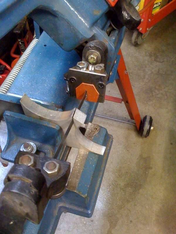
The tool was opened just slightly by wedging open and used a large pair of circlip pliers to gently draw the tappet into the clamping fixture.
Once in the fixture I threaded a short 5/16 bolt in the other end of the cross drilled hole to give me a place to place a pair of sockets and extensions that held the fixture in position so the lifter body could be worked back and forth while the tappet was held in place. In the beginning, I didn't think the lifter body would move. It was unbelievably tight. Finally got it to begin moving. I quickly understood why the tappets break when trying to remove ballooned lifter bodys. I struggled for close to an hour and only got it up about .020". at this point I went in for dinner and thought on it for a bit. Went to the super market and bought dry ice to pack into the lifter body in hopes of a couple tenths shrinkage while the holding fixture warmed with a heat gun to possibly gain a few tenths. This seemed to help and the lifter body began of lift out of the tappet with rotating movement while pulling up and against the holding fixture. Patience, thought, and some home made tooling prevailed! I was sweating bullets for a while, wasn't sure it would extract. I can't begin to explain how pleased I am to succeeded in this phase of the planned repairs. After considerable clean up to ensure there were no contaminants the new lifter was test fitted. It slid right in and fit very well. What a delightful sight to see at 12:30 am in the morning. A much longer time in the garage after a day at work than planned. I don't know if anyone has done this, but I sure am happy to not have to remove the front of the engine, pan, and camshaft! If this is a new approach to an occasional problem I hope I have described it well enough for others to try. Attach file:  (35.70 KB) (35.70 KB)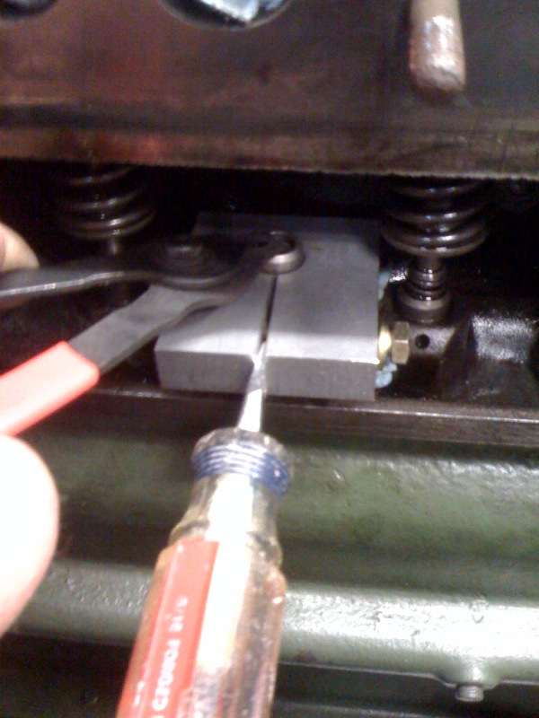 (34.13 KB) (34.13 KB) (33.99 KB) (33.99 KB)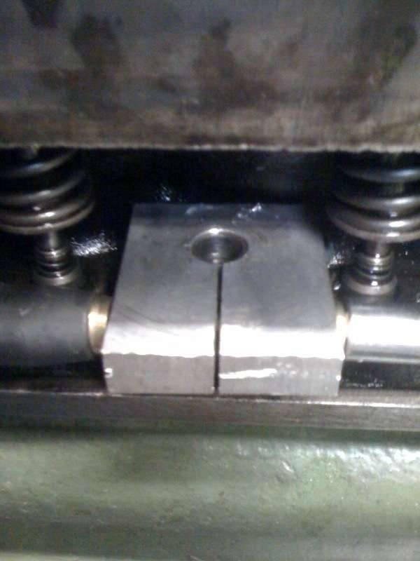 (32.08 KB) (32.08 KB)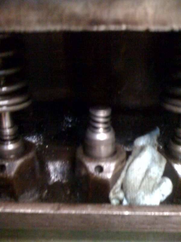
Posted on: 2011/5/12 3:23
|
|||
|
||||
|
Re: 1940 Super 8 160 Model 1803 Project
|
||||
|---|---|---|---|---|
|
Home away from home

|
Congratulations! If my mechanic had access to your clever invention before he shattered the lifter, it might have saved me a bundle.
Posted on: 2011/5/12 8:30
|
|||
|
||||
|
Re: 1940 Super 8 160 Model 1803 Project
|
||||
|---|---|---|---|---|
|
Webmaster

|
Another quality tool produced by Jim's Wheel, Tire, Fabrication, CAM repair, and Moulton Farming Company!
Posted on: 2011/5/12 11:32
|
|||
|
-BigKev
1954 Packard Clipper Deluxe Touring Sedan -> Registry | Project Blog 1937 Packard 115-C Convertible Coupe -> Registry | Project Blog |
||||
|
||||
|
Re: 1940 Super 8 160 Model 1803 Project
|
||||
|---|---|---|---|---|
|
Forum Ambassador

|
Never enountered that lifter problem - I suppose it can occur by failure to check and adjust the lifter/valve stem clearance after a valve replacement or grind. In any case, clever tool and nice solution.
Great stuff, dry ice. I used to use it regularly when fitting new valve guides, and also on my Caribbean I had to use it in the crankshaft snout to reinstall the vibration damper.
Posted on: 2011/5/12 12:12
|
|||
|
||||
|
Re: 1940 Super 8 160 Model 1803 Project
|
||||
|---|---|---|---|---|
|
Forum Ambassador
|
"Never encountered that lifter problem - I suppose it can occur by failure to check and adjust the lifter/valve stem clearance after a valve replacement or grind..."
Dave, no that is not possible. The lifter to valve stem clearance equates to the valve not sinking the lifter plunger deep enough into the lifter body resulting in a noisy valve, or the valve sinking the plunger to deep into the lifter body resulting in a valve that is not fully resting on the valve seat with the results being leaking cylinder and possibility of exhaust valves burning because of no ability to exchange heat into the block. The condition that leads to a lifter body ballooned into a tappet body is a very stuck valve. The stuck valve forces the lifter plunger with force resulting in hydraulic pressures far exceeding the structural limits for the given material and wall thickness of the lifter body. This spike in pressure effectively balloons the lifter body, swaging it into the tappet body. I would only imagine this condition in engines with seriously stuck valve(s). This is a condition I first thought about after reading JD's thread and discussing in the chat room with him. I then discussed this with Ross Miller in late November where Ross described encountering the same situation resulting from stuck valves. I remember Tom (previous owner) saying that he had issues with number 6 exhaust sticking. When I discovered it was only #6 exhaust that was leaking excessively and not pumping up I braced myself for difficulty removing the lifter body. I am providing this comprehensive explanation for those who might have a Packard straight 8 with hydraulic lifters might understand the risk of major hydraulic valve lifter / tappet damage, and difficulty removing lifter bodies because of cranking / running with stuck valves. I am so grateful to JD and Ross (and Packard Info. of course) for sharing their experience so I could avoid further damage and much more work.
Posted on: 2011/5/12 19:56
|
|||
|
||||
|
Re: 1940 Super 8 160 Model 1803 Project
|
||||
|---|---|---|---|---|
|
Forum Ambassador
|
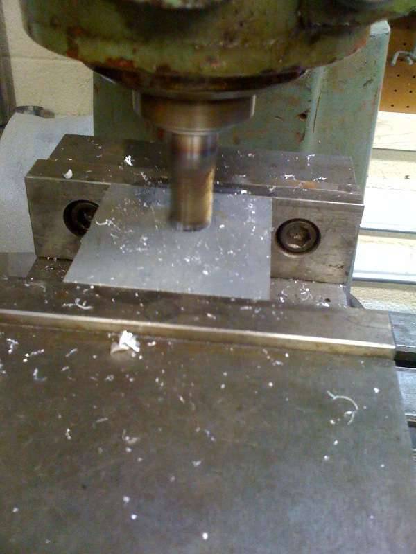
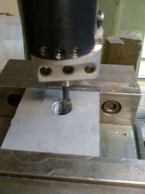
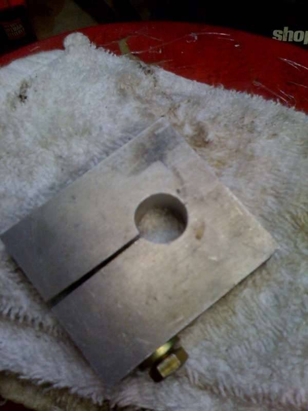
After taking a night off to do some research on the valve gauge block situation I got back at it after dinner out with friends this evening. Firstly, I find according to the 1940 Super 8 owners manual / service manual supplement you need only the tappet installed with no oil in it what so ever and to depress the plunger all the way down; measuring with feeler gauge no less than .030" and no more than .070" clearance. I was very surprised to learn this given all the discussion about the gauge block method. I am also surprised to find that Packard engineers wanted the lifter plunger sunk that deep into the lifter body, but that is what they wanted and they built a fine silent running engine that provided great long-term service.
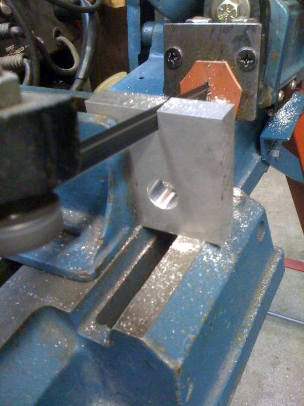
One of our forum members was kind enough to provide gauge block specs today. I compared the gauge block specs to fully compressed lifter and what do you know... they are exactly the same! So, after all the discussion about the gauge block, and understanding that this tool would make it very quick and efficient in checking valve stem to tappet clearance, I felt compelled to go ahead and make one to use this evening. Grabbed some steel and got after it. Not a tough or terribly time consuming project. Below are a few images of DIY gauge block production. Attach file: (41.07 KB)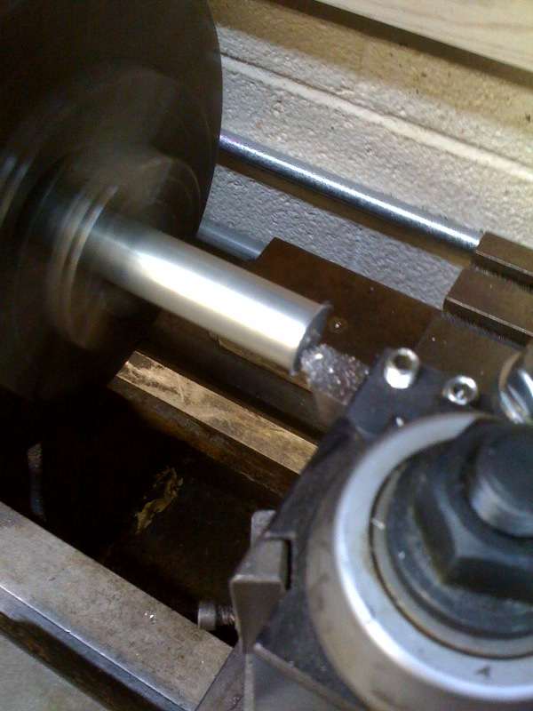 (44.74 KB) (44.74 KB)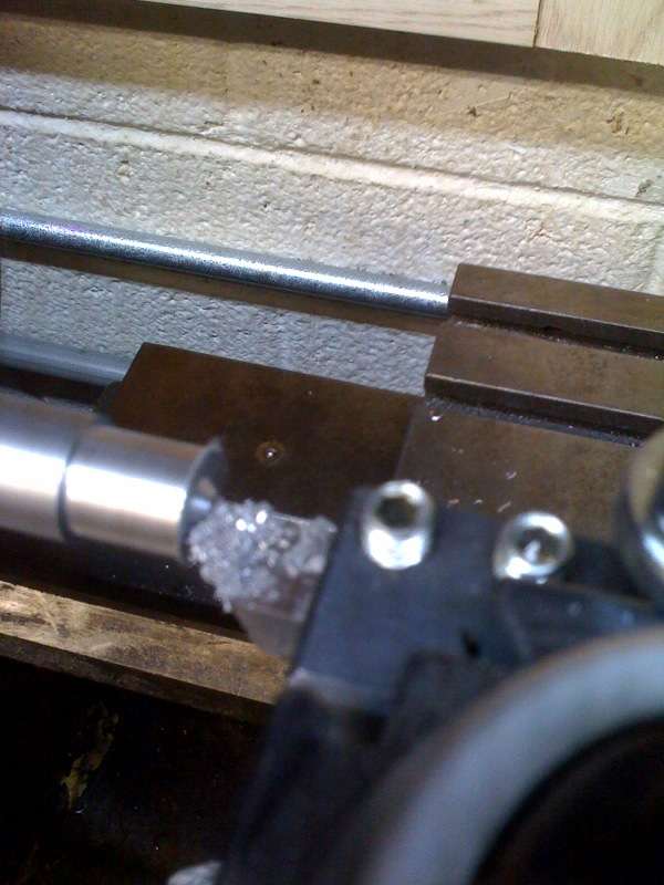 (41.74 KB) (41.74 KB)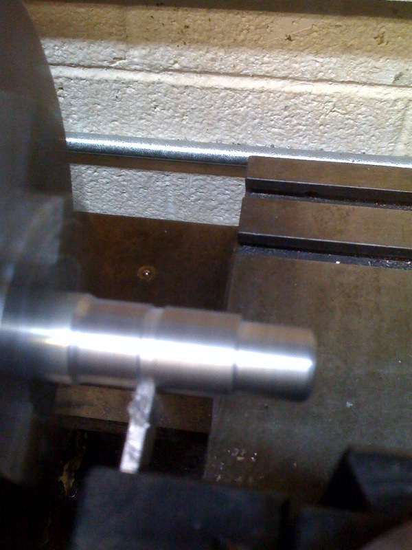 (41.74 KB) (41.74 KB)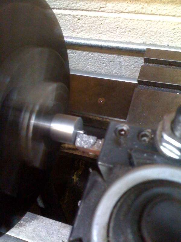 (38.17 KB) (38.17 KB)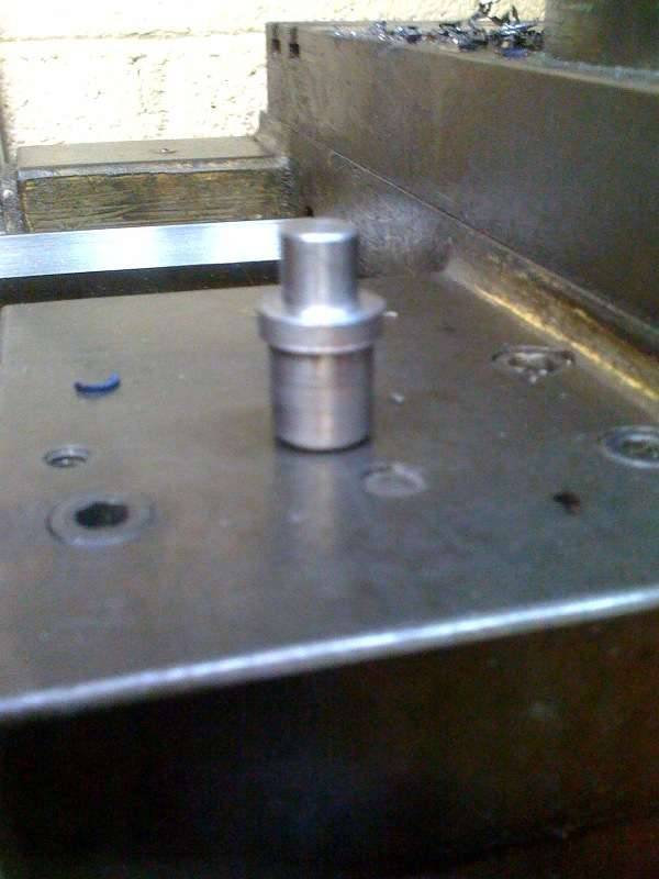
Posted on: 2011/5/14 2:33
|
|||
|
||||
|
Re: 1940 Super 8 160 Model 1803 Project
|
||||
|---|---|---|---|---|
|
Forum Ambassador
|
Armed with gauge block in hand and feeler gauge in the other, I performed the checks. As luck would have it the .030" easily went in and the .070" would not. How nice to know the valve to lifter clearance is perfect and to also be reassured the damage was not caused by improper clearances or improper assembly.
I also repeated the check simply using the empty replacement lifter and said feeler gauges fully depressing the lifter plunger and checking go/no go and got perfectly identical measurements and results. So, we have learned that while the gauge block is neat to have, it seems the plunger depth can be set with the emptied and compressed lifter assembly installed. A very interesting and enlightening exercise. Attach file: (30.12 KB)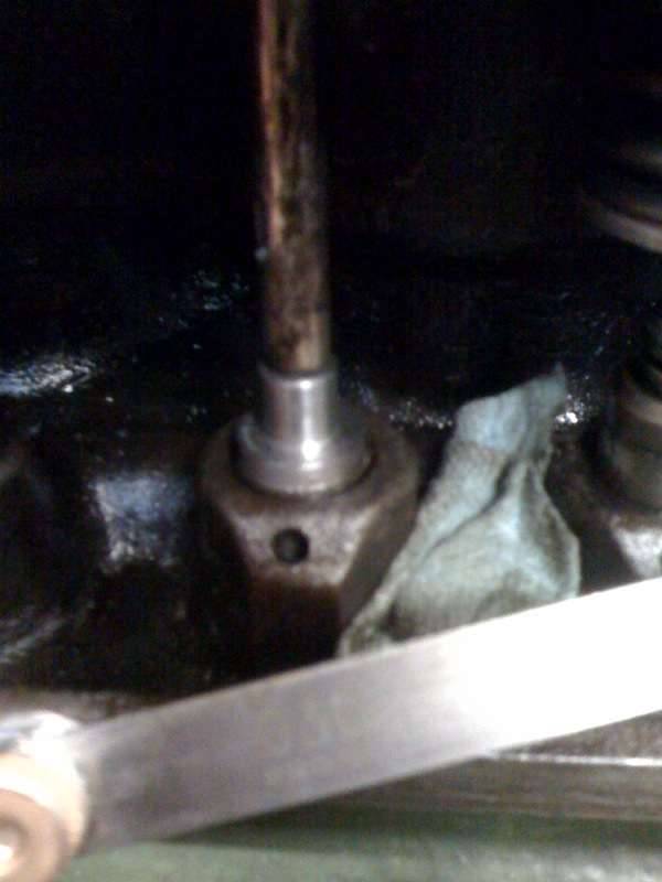 (29.62 KB) (29.62 KB)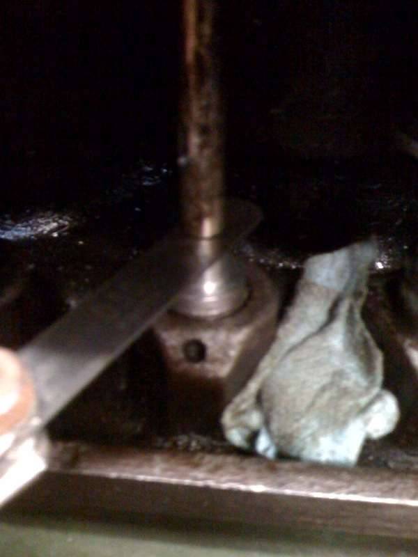
Posted on: 2011/5/14 2:37
|
|||
|
||||
|
Re: 1940 Super 8 160 Model 1803 Project
|
||||
|---|---|---|---|---|
|
Home away from home

|
Cool to see that process, Jim. Wow. I want to see your garage. A garage with REAL equipment.
But in the DIY department, the clueless innovate. When I was going through my lifters, that little oil hole has to be absolutely clean for the plunger to go down. I bought my plug gauge from the Pacific NW Region of PI. Here are the instructions they sent. "Place the gauge in the lifter body and while holding the valve down on its seat, check the clearance between the valve stem and the gauge using a feeler gauge. The clearance should be more than .030 inch and less than .070 inch. Repeat for each valve. Be sure to see that each piston is at the top of its compression stroke when checking the corresponding valves for clearance. When installing the hydraulic lift into the tappet, it is advisable to have removed all of the oil from inside the hydraulic unit. Otherwise, the valve may be held open until the excess oil escapes from the lifter. With good tight lifters this could take some time. The lifters will pump back up over a period of time. This can take as much as 20 to 30 minutes to become totally quiet depending on oil pressure." I realize you said most of that. I think I read in one of the service manuals that it can take an hour for the lifters to pump up. As a clueless DIYer who was terrified of mismatching plungers after reading all the warnings (i.e. If mismatched, return to factory.), I used a little berry box with a masonite bottom. Turned it upside down and drilled 1/2" holes in it to hold the lifters while I cleaned them one at a time. (It's spent some time in the paint room since, holding smaller items for painting.)The lifters fit in the hole like the gauge does in the small picture. And to make sure I didn't lose any keepers, I used a couple of sizes of rubber plugs to fill the holes in the block. I know, stone age, but for me, it worked. Joe Attach file: (86.58 KB)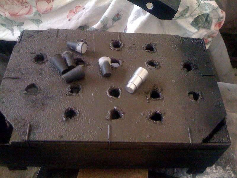 (34.06 KB) (34.06 KB)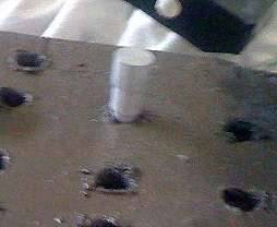
Posted on: 2011/5/14 10:19
|
|||
|
||||
|
Re: 1940 Super 8 160 Model 1803 Project
|
||||
|---|---|---|---|---|
|
Forum Ambassador
|
Congrats! Good preparation and thinking, you've done your homework and what most of us who have done dozens of these valve jobs routinely do. I have a rack to retain the valves in the order they were in the engine, and ditto for the lifters. As to remembering to put corks or similar into the oil return holes, a lot of folks have learned that the hard way.
Yes, using the gauge block is much simplier, whether it's more or less accurate I don't know but the fact that Packard dropped the recommendation of the alternative method probably has some basis. Some one earlier, perhaps in this thread, made a comment about Packard's designing these lifters or something like that - Packard didn't design them, they were designed, patented and manufactured by Wilcox-Rich and are of the same design though slightly different than the Wilcox-Rich units used in the flathead Cadillac V8 (345 ci). Pierce Arrow had hydraulic lifters in the in-line 8s well before most anyone else - don't know who made these units but if anyone knows, I'd like to hear.
Posted on: 2011/5/14 13:28
|
|||
|
||||


